After doing some research we got our solar system in April 2023. We went with a company that was using AlphaESS equipment and one of the reasons for choosing that particular installer was their neat work – a neighbour of ours allowed us to have a look. Our system had to be neat since we were planning to install it in a customer facing area of our little family business.
After enjoying the free electricity during the summer I started to get curious. Being a bit old fashioned I was wondering if and how the system can be monitored and controlled without AlphaESS’ cloud backend. So in December 2023 I read a lot about Modbus RTU, Modbus TCP, ioBroker and Home Assistant (HA). After trying both ioBroker and HA I decided to go with HA – the more popular home automation solution. I installed a test system in a VirtualBox and was able to monitor the AlphaESS system shortly after. I ordered a HA Green straight away, knowing that this was something I’d like to run 24/7.
It didn’t take long until I added the logic to run a scheduled force discharge of the batteries at night (from 23:30-02:00) – just before recharging the batteries again (from 02:00-06:00). This schedule is running since January 2024 now and hasn’t had a single hiccup.
At this stage I decided to write things down, both for my own documentation and also to share my learnings – so here we go…
Update: as of end of August 2024 my HA instance isn’t hosted on the HA Green anymore but in a Proxmox VM on a Beelink MINI S12 PRO.
Update: as of start of September 2024 the integration contains automations to prioritise grid feed-in over battery charging to reduce clipping and maximise feed-in.
Get the latest copy of integration_alpha_ess.yaml here:
https://projects.hillviewlodge.ie/_alphaess/integration_alpha_ess.yaml.
Also make sure to download a fresh copy of alphaess_view.yaml and power_diagram.yaml/power_diagram_extended.yaml each time a new version of integration_alpha_ess.yaml has been released.
Note: I will post details about updates/enhancements in the official AlphaESS Facebook Group.
Useful AlphaESS reference documentation:
AlphaESS-ModbusRTU&TCP.pdf
AlphaESS-ModbusDispatchFunction.pdf
AlphaESS-ModbusProtocol.pdf
AlphaESS-HouseholdModbusRegisterMapTable.pdf
AlphaESS-HouseholdModbusRegisterParameterList.pdf
Disclaimer
Use the provided information at your own risk!
Be careful when making changes and double and triple check everything – writing inconsistent data into your AlphaESS Inverter’s Modbus registers might cause unexpected results which could damage your system!
I can’t offer official support but I’ll try to help if you need additional details, instructions or troubleshooting.
Tested on SMILE5, SMILE-G3-S5 (in fact, one many of the G3 series models) and SMILE-Hi10 but according to AlphaESS’ documentation the register addresses and values are consistent through all supported models. Additionally is has been tested on some older models like the SMILE-B3 and SMILE-B3-PLUS (using a Modbus RTU to Ethernet converter), which offers limited information/functionality due to slightly slower access and the nature of being AC coupled.
Warning: local laws and regulations, particularly regarding grid feed-in limitations, might restrict the use of certain functionalities in this integration. It’s your responsibility to ensure your usage of this integration complies with all applicable rules and regulations.
Warning: avoid excessive write cycles of Modbus registers that are stored in the Inverter’s flash memory since that will degrade the chip. The affected registers are the ones that store general system specific setting and survive system restarts, e.g. Charging and Discharging Periods and their Cutoff SoCs, PV Capacity, Max Feed to Grid percentage, Grid Safety settings, etc. The Dispatch Mode related registers are not affected, these are not stored in the flash memory.
Intended Audience
The intended audience for this guide are tech savvy persons, wanting to get more information out of their AlphaESS system without depending on AlphaESS’ cloud backend or persons, planning to access parts of the systems that cannot be accessed via App/WebUI.
Prerequisites
- Your Inverter must be connected via LAN port (not Wi-Fi). If wired network is not available you can use Powerline (€40) or a Wi-Fi Repeater with an Ethernet port (€20) to extend your network alternatively.
- Home Assistant release 2024.10 or newer.
- Basic TCP/IP knowledge: this includes an understanding of what an IP address is, the function and identification of ports, and methods for locating devices within a home network.
- Proficiency in setting up and modifying Home Assistant and YAML files: this involves skills in configuring Home Assistant and the ability to edit YAML files, which are often used for configuration settings.
- I am providing a preconfigured YAML file containing the majority of the AlphaESS systems available information and some configuration options. If this doesn’t cover your specific use case you will either have to extend the file with the bits relevant to you yourself or contact me and I will assist in modifying the file.
- Understanding of electrical units: a fundamental grasp of key electrical concepts and units such as kilowatts (kW), kilowatt-hours (kWh), watts (W), volts (V) and amperes (A).
Coding/programming skills are not required.
Does your AlphaESS Inverter have Modbus TCP?
Identify your Inverter’s IP address and check if port 502 is open. That indicates that Modbus TCP is enabled and listening. If the port is closed check if it can be enabled via the Inverter’s control panel or reach out to support to get it enabled (Remote configuration or firmware update).
Modbus TCP capable Inverters:
SMILE5, SMILE-Hi5, SMILE-Hi10, SMILE-G3-S3.6/B5/S5, essentially all G3 models.
If your Inverter doesn’t have Modbus TCP it might have Modbus RTU (RS485). In that case a converter can be used, there are Modbus RTU to USB (ca. €20, e.g. Waveshare USB to RS485 Converter) or, preferable, Modbus RTU to Ethernet (ca. €50, e.g. Protoss PE11, USR-W610, Waveshare RS485 to RJ45 Ethernet Converter) converters available. I have limited experience with any of these converters and therefore wouldn’t be able to provide much help.
Using a Modbus RTU to USB converter will require changes to the provided YAML file (see Appendix).
Modbus RTU capable Inverters:
SMILE-B3, SMILE-B3-PLUS, SMILE-i3, SMILE-T10 and older models of SMILE5, SMILE-Hi5, SMILE-Hi10, SMILE-G3-S3.6/B5/S5.
Note: the list of Inverters above was taken from official AlphaESS documentation but seems to be incomplete, esp. the Modbus TCP capable ones. While a specific model is not listed it might still support Modbus TCP, carrying out a port 502 check as described above might still return a positive result.
Note: prior to buying any dedicated Home Assistant (HA) hardware a virtual test environment can easily be configured using VirtualBox/VMware Workstation/Hyper-V on a PC or Laptop.
Feedback from some Modbus RTU to Ethernet converter users:
- SMILE-B3 with USR-W610: Read registers OK/Write registers limited
- SMILE-B3 with Protoss PE11: Read registers OK/Write registers OK
- SMILE-B3-PLUS with Protoss PE11: Read registers OK/Write registers OK
- SMILE5 (AL200) with Protoss PE11: Read registers OK/Write registers not OK (extremely slow, not usable)
- SMILE5 (AL500) with Waveshare RS485 to RJ45 Ethernet Converter: Read registers OK/Write registers OK-ish (slow, potentially causing timing issues when trying to use Excess Export)
Setup
The following instructions apply to Modbus TCP enabled Inverters only (video of the HA configuration steps 4 – 14):
- Make sure your Inverter is connected via LAN port (not Wi-Fi).
- Configure a DHCP Reservation on your router, ensuring your Inverter has a static IP address assigned.
- Get a HA instance installed, either in a virtual test environment or a HA device.
- Install “File editor” under “Settings/Apps/Install app”, enable “Start on boot” and “Show in sidebar”, click “Start”.
- Get the latest copy of integration_alpha_ess.yaml here:
https://projects.hillviewlodge.ie/_alphaess/integration_alpha_ess.yaml - In “File editor” use “Browse Filesystem” to select the “packages” folder (use “New Folder” to create if required).
- Use “Upload File” to copy integration_alpha_ess.yaml to the “packages” folder.
- SMILE-B3 & SMILE-B3-PLUS users: edit integration_alpha_ess.yaml, search for SMILE-B3/SMILE-B3-PLUS (12 occurrences) and adjust according to the comment.
- In “File editor” use “Browse Filesystem” to select configuration.yaml, append the following lines, then “Save”:
homeassistant:
  packages: !include_dir_named packages
- In “File editor” use “Browse Filesystem” to select secrets.yaml, append (without quotes) the following lines, then “Save”:
alphaess_modbus_host_ip: "your Inverter’s IP Address" alphaess_modbus_host_port: 502 alphaess_modbus_slaveId: 85 - Perform a restart of your HA (“Settings/⋮/Restart Home Assistant”).
- Get the latest copy of alphaess_view.yaml here:
https://projects.hillviewlodge.ie/_alphaess/alphaess_view.yaml - In HA select “Settings/Dashboards/Add dashboard/New dashboard from scratch”, populate “Title” with “AlphaESS” and “Icon” with “mdi:solar-panel”, click “Create”.
- Click on the newly created AlphaESS dashboard and select “Edit dashboard/Edit view/⋮/Edit in YAML”. Select the default content and replace it with the content of alphaess_view.yaml. Click “Save”, then “Done”.
Configuration
Currently the only required configuration option is selecting your Inverter’s AC Limit. This setting will adjust the range of the Force Charging/Force Discharging/Dispatch Power sliders and is also required for the Excess Export automation to function properly.
Make sure to select the correct value for your Inverter:

Updating from a previous version
- Take a fresh copy of integration_alpha_ess.yaml, replace it on your HA instance, restart HA.
- Take a fresh copy of alphaess_view.yaml, in HA’s Overview select the AlphaESS view, select “Edit dashboard/⋮/Edit view/⋮/Edit in YAML, replace the content with the content of alphaess_view.yaml (overwriting the old code).
- Take a fresh copy of power_diagram.yaml OR power_diagram_extended.yaml (which ever you plan to use), in HA select the AlphaESS dashboard, select “/Edit dashboard/⋮/Raw configuration editor”, replace the content with the content of power_diagram.yaml OR power_diagram_extended.yaml (overwriting the old code).
Dispatch/Force Charging & Discharging/Force Import & Export
Warning: the Dispatch/Force Charging/Force Discharging/Force Export automations do not honor the configured grid feed-in limitation (Max Feed to Grid). Local laws and regulations might restrict the use of these automations in your country.
Dispatch Mode details and potential use cases:
- Battery only Charges from PV (1)
Behaviour: the battery charges from PV Output only, with the set max. amount of Power.
Required: Duration/Power
Details/Use cases:
This mode can be used to throttle charge the battery from PV Output. Power must have a negative value, positive Power values have no effect. The battery does not discharge/serve house loads in this mode. Excess PV Output will be fed to the grid. - State of Charge Control (2)
Behaviour:- Power > 0W (positive) & Cutoff SoC < Battery SoC: the battery discharges with the set amount of Power until Cutoff SoC is reached. The discharged power will go to the house loads and any excess will be exported to the grid. If available, PV Output will contribute.
- Power < 0W (negative) & Cutoff SoC > Battery SoC: the battery charges from the grid with the set amount of Power until Cutoff SoC is reached. If available, PV Output will contribute.
Required: Duration/Power/Cutoff SoC
Details/Use cases:
This mode can be used for any type of charging or discharging, it’s the mode that the Force Charging and Force Discharging automations in the Charging card facilitate. It’s also the mode that Excess Export facilitates. - Load Following (3)
Behaviour: default behaviour with a throttled battery charge/discharge rate.
Required parameters: Duration/Power
Details/Use cases:
This mode is the same as the default behaviour but limits the battery charge/discharge rate to the set Power. Power is set as an absolute value, the prefix (+/-) is being ignored.PV Output exceeding the set Power plus the house load will be capped, once the battery is fully charged the PV Output will be capped at the house load – following the load.The mode seems to be identical to Normal Mode (5). - Maximise Output (4)
Behaviour: grid feed-in is maximised.
Required parameters: Duration
Details/Use cases:
The system will maximise grid feed-in by discharging the battery. If available, PV Output will contribute. - Normal Mode (5)
Behaviour: The mode seems to be identical to Load Following (3).
Required parameters: Duration/Power
Details/Use cases: see Load Following (3). - Optimise Consumption (6)
Behaviour: battery force charges at full power.
Required parameters: Duration
Details/Use cases:
This mode maximises grid consumption, the house load will be served by the grid and the battery will start charging from the grid, while the PV Output is contributing. - Maximise Consumption (7)
Behaviour: PV Output is disabled & battery force charges at full power.
Required parameters: Duration
Details/Use cases:
In some countries electricity providers pay for using from the grid (negative prices). This mode essentially disables the solar panels and maximises grid consumption, the house load will be served by the grid and the battery will start charging from the grid, while the PV Output is throttled to zero. - No Battery Charge (19)*
Behaviour: battery charging is disabled.
Required parameters: Duration
Details/Use cases:
This mode disables charging the battery, while it’s still able to serve house loads. This mode in combination with Max Feed to Grid equals 0% can be used to eliminate grid feed-in while limiting the battery charging (to reduce battery cycles).
* Dispatch Mode 19 is not available on some older Inverter models.
- PV Switch*
PV Switch can be used to deactivate the solar panels and can be combined with each of the Dispatch Modes.
Details/Use cases:
The typical use case is periods of negative electricity prices. Setting PV Switch to off will disable the PV Output, combined with e.g. State of Charge Control (2) and Power = 0 the house load will be served by the grid. This can be used during a negative price period when there is an even better deal expected for later in the day – at which stage Maximise Consumption (7) would the Dispatch Mode of choice.
* PV Switch does not have any effect on some older Inverter models.
Force Charging vs. Force Import
- Force Charging
Behaviour: the power slider value defines the battery charge rate. The power imported from the grid will be the chosen value plus the house load.
Use case:
This automation is the standard way of charging the battery. - Force Import
Behaviour: the power slider value defines the grid import rate. The battery charge rate will be the chosen value minus the house load. It allows users to set a fixed grid import value which stays constant, adjusting to house load and solar output fluctuations. The automation will pause that mechanism when the house load exceeds the set power rate (to avoid pulling more than the limit from the grid). The battery will then take over serving the house load. The mechanism will resume once the house load drops below the set power rate. Additionally any solar power will contribute to loading the battery.
Use case:
In some countries (e.g. Belgium) exceeding a specific grid import rate (e.g. 3 kW) is not desired (to reduce the load on the grid) and users are being financially penalised heavily for exceeding that limit.
Force Discharging vs. Force Export
- Force Discharging
Behaviour: the power slider value defines the battery discharge rate. The power sent to the grid will be the chosen value minus the house load.
Use case:
This automation is targeted at users who receive high payments for feeding into the grid. Users typically set the power slider to the highest possible value, maximising the profit. - Force Export
Behaviour: the power slider value defines the grid feed-in rate. The battery discharge rate will be the chosen value plus the house load. It allows users to set a fixed grid feed-in value which stays constant, adjusting to house load and solar output fluctuations.
Use case:
This automation is targeted at users of “no grid consumption” plans, like GloBird ZEROHERO (0.03 kWh/h), and users who are trying to reduce/eliminate the system’s grid consumption by running a constant trickle export, essentially offsetting the fluctuation around the 0W baseline to e.g. -200 W. Users typically set the power slider to very small amounts, e.g. 0.2 kW.
Excess Export (Feed-in Prioritisation)
Warning: the Excess Export automation does not honor the configured grid feed-in limitation (Max Feed to Grid). Local laws and regulations might restrict the use of this automation in your country.
Enabling “Excess Export” will change the Inverter’s load serving priority, the default being the sequence: House Load > Charge Battery > Export to Grid. Once enabled the Inverter will prioritise feed-in, the sequence will be: House Load > Export to Grid > Charge Battery.
Use cases:
- Clipping reduction/elimination
- Grid feed-in maximisation (for countries with grid feed-in payments higher than consumption tariffs)
Positive side effect: potentially less battery cycles.
What is “clipping”?
Below is a visualisation of clipping and the effect of the “Excess Export” automation. Clipping occurs in oversized systems, where the panels could generate more energy if the Inverter had the ability to send it somewhere.
The first diagram (May 15) shows that around 7:00 a.m., solar production exceeds the house load, and the battery begins to charge. Around 12:30 p.m., the battery is full, and solar production is throttled back because the Inverter (here, a G3-S5) can only handle 5 kW AC. The same effect also occurs with larger Inverters, then, for example, starting at 10 kW.
In the second diagram (May 16), “Excess Export” is active. Starting at 7:00 a.m., any excess power is fed into the grid, resulting in delayed battery charging. At 10:00/10:30 a.m. the solar production exceeds the AC amount the Inverter can handle – anything above that is sent to the battery. The battery never reached 100% SOC on that day, so no energy was lost through clipping.
On both days, the starting SOC was 50% and the solar production was practically identical. The additional yield by preventing clipping is significant, on good days, my system achieves over 20%. The potential additional yield depends on the specific system: Inverter model, oversizing, battery size. The “Excess Export” mode also helps to extend battery life, as the battery isn’t charged to 100% every day.

Note: If you are planning to use this automation and your Inverter has a different rating, make sure to select the correct value for your Inverter:
Power Diagram (optional)

Get the latest copy of power_diagram.yaml here:
https://projects.hillviewlodge.ie/_alphaess/power_diagram.yaml.
There’s also an extended version available here (adding additional charts):
https://projects.hillviewlodge.ie/_alphaess/power_diagram_extended.yaml.
As a prerequisite for the Power Diagram download the current apexcharts-card.js from https://github.com/RomRider/apexcharts-card/releases/latest.
The following steps are required to set up the Power Diagram (video of the HA configuration steps 3 – 6):
- In “File editor” use “Browse Filesystem” to select the “www” folder (use “New Folder” to create if required).
- Use “Upload File” to copy apexcharts-card.js to the “www” folder.
- In HA select “Settings/Dashboards/⋮/Resources/Add resource” setting “URL” to “/local/apexcharts-card.js” and selecting “JavaScript module” as the “Resource type”.
- Restart HA.
- In HA select “Settings/Dashboards/Add dashboard/New dashboard from scratch”, populate “Title” with “AlphaESS Power Diagram” and “Icon” with “mdi:chart-areaspline”, click “Create”.
- Click on the newly created AlphaESS Power Diagram dashboard and select “Edit dashboard/⋮/Raw configuration editor”. Select the default content and replace it with the content of power_diagram.yaml or power_diagram_extended.yaml. Click “Save”, then “Close”.
Credits for the Power Diagram go to Daniel Young and his brilliant work on the Alpha2MQTT integration (https://github.com/dxoverdy/Alpha2MQTT).
Note: if you decided to change entity names in the provided integration_alpha_ess.yaml file you will have to adjust these in the power_diagram.yaml accordingly.
Appendix
Potentially required YAML modifications for a Modbus RTU to USB converter (where /dev/ttyUSB0 is depending on your individual HA hardware):
Change:
modbus:
  - name: modbuspvsystem
    type: tcp
    host: !secret alphaess_modbus_host_ip
    port: !secret alphaess_modbus_host_port
    message_wait_milliseconds: 10 # Waittime between 2 messages
    timeout: 10 # Timeout in seconds before connection is closed
    delay: 1 # Delay in seconds at startup
To:
modbus:
  - name: modbuspvsystem
    type: serial
    port: /dev/ttyUSB0 #USB FTDI device connected to the Inverter’s CAN/RS485 Modbus port
    baudrate: 9600
    bytesize: 8
    method: rtu
    parity: N
    stopbits: 1
    message_wait_milliseconds: 10 # Waittime between 2 messages
    timeout: 10 # Timeout in seconds before connection is closed
    delay: 1 # Delay in seconds at startup
Axel.
One thing that’s not explained is changing the sensor names to match your own sensors in the Daily power diagram. My entities had different names. Other than that the Power diagram works great. My ideal goal is to curtail my solar feed in when my wholesaler (Amber) turns negative. Im looking to curtail feed in but power the house load and charge the battery.
Love your work
Good point, Glenn. Thanks for the feedback 🙂 I’ve added the missing information now.
I have an Alpha ESS Storion-SMILE-T10, I managed to get the ModBus communication working. But when I want to modify the registers, the device does not respond to the command and ends with a timeout.
Am I doing something wrong or do I need to enable the write somewhere first?
Reading:
send: 0x55 0x3 0x8 0x50 0x0 0x1 0x8b 0xaf
recv: 0x55 0x3 0x2 0x0 0x6e 0x8 0x64
Saves:
send: 0x55 0x6 0x8 0x50 0x0 0xd2 0x6 0x32
Thank you for your help
Hiya Frenky, from what I can see this question isn’t about using my integration but some generic form of reading/writing Modbus registers. I am not aware of any writing restrictions that have to be disabled. The only thing I do know is that initiating some processes on the AlphaESS might require the commands to be sent in the correct sequence – for example when initiating a Dispatch/Force Discharge (Dispatch Mode has to be the last command) . What are you actually trying to do?
Hallo Frenkie. I have the same T10, but I have trouble probably with the dispatch connector. Which pins can I use?
Thank you for the answer. Ivo
I learned today from ESS support that Storion-SMILE-T10 has only the possibility of reading via ModBus (changing values – writing is not possible).
😞
Is there a way to prevent the Alpha from charging via grid at all?
Background: If you do have a secondary plant, another battery or anything that is capable of feeding energy into the grid, chances are that the Alpha is sucking this up because of the super conservative settings.
Hi Thoralf, unfortunately I’m not aware of a method to prevent that. I also don’t have a way of testing anything like that.
Any chances to integrate that into Github / HACS Repo? I would love to have it additionally to the cloud version or even better, have both options in one repo. I created an issue here (https://github.com/CharlesGillanders/homeassistant-alphaESS/issues/119), but Charles seems not to have modus to test it.
Hi Marius,
I currently don’t have any plans to publish on GitHub (for several reasons) and I don’t have the slightest clue about how to create HACS Repos – but there is no need for either. My integration shouldn’t have any issues coexisting with Charles’s integration.
Cheers,
Axel
Finally Installed your Integration in HA today.
Love it. Ive been wanting a level of control over my Alpha System for ages.
One thing i found is if i make a change in the integration. It reflects correctly in the Alpha APP. But if i make a change in the Alpha APP, it doesn’t .
Is there any auto refresh that syncs command from the app to show correctly in HA. or is this because commands in the APP are based on API commands.
Hey Glenn, great to hear that you love it 😉
I didn’t notice that issue and I ran a quick test a minute ago: I changed the “Discharging Cutoff SOC” in the WebUI and also in the App – both updated fine in the HA integration after seconds. Which particular values were you testing with?
Hello, first of all, thank you very much for the great work.
I have had the integration running for a few days now and I’m very satisfied. Previously, I was using the original Schnitzelweck92 variant.
For my understanding, I wanted to ask whether the Excess_Export automations relate to the approach discussed here: https://www.storion4you.de/thread/903-ladezeit-einstellen-mit-nur-pv/?pageNo=3 regarding saving or reducing unnecessary grid power consumption in the morning and evening when there is little solar energy available? Or does it pursue a different approach?
thank you!
Hi Wolfgang,
thank you very much 😉 You are right, the topic discussed there is related – what I’m trying to achieve is this: here in Ireland we are getting well paid for feeding into the grid. So I am using that functionality to maximise export by pushing out the batteries being full to as late as possible. That way I can reduce or even eliminate clipping.
The same logic can also be used to reduce or eliminate the unnecessary grid consumption during dusk and dawn – I just didn’t implement that because I don’t have a use case for that.
PS: I’ve made some minor changes to the YAML today, so I’d recommend using the new version.
PPS: I’m actually SaaX on the Storion4you forum 😉 Feel free to contact me via Email and I’ll be able to respond in German.
Cheers,
Axel
This is really great. Thanks!
I’m curious if you can give me any greater insight into the details of the different dispatch modes. I did read the Alpha doc and it gives only very high level descriptions which don’t seem to be enough detail.
– Modes 1, 2, & 3 seem pretty clear.
– For mode 4, will it charge the battery if there is excess PV? Or will excess PV go to the grid?
– Why is the description of mode 5 the same as mode 3? Are these really identical?
– in mode 7, what happens to PV.
What I want is to stop charging at less than 100% to extend battery life. I want to use PV as much as possible to reach this threshold, but if PV can’t get there before my rates increase, then I’ll use grid power to get there. For me, 00:00 – 15:00 is cheap from the grid and 15:00-24:00 is expensive. I can use mode 1 to normally get to this threshold before 15:00. I monitor the SOC and if it reaches my threshold before 15:00, then I switch to SOC control (mode 2) with a dispatch SOC value so the Alpha doesn’t exceed my threshold, and all my excess PV goes to the grid. I’ll also switch to mode 2 a bit before 15:00 so that I’m sure my batteries are topped up to my threshold. But once I get to 15:00, I don’t know what mode and parameters to use. Mode 3 (load follow) is basically what I want, but when there is excess PV (which there usually is) then it continues charging the battery to 100% which I don’t want. Unfortunately the Dispatch SOC value is only used by mode 2 and not by other modes. I want a mode where PV powers the house loads, excess PV gets pushed to the grid, if there is not enough PV then the battery will power house loads, BUT the battery won’t be charged.
Any thoughts??
Hi David,
unfortunately I have not looked into any of the other dispatch modes since 2 does everything I needed. So I don’t know how or if you can achieve what you’re looking for.
Regarding mode 5 I have found this information (translated from German): The function limits the performance of the battery when charging and discharging to the values set in registers 0881H/0882H. Otherwise charging/discharging takes place automatically. (Source: https://www.storion4you.de/thread/903-ladezeit-einstellen-mit-nur-pv/?postID=14452)
Maybe the guys on that forum have an idea, worth a try…
Cheers and good luck,
Axel
Thanks for the response. And I’ll definitely look at that link you sent for mode 5.
Of course, just like Murphy’s Law, as soon as I posted my question above, I came up with an idea. I just tested it out this morning and I am now able to achieve what I want using modes 1, 2, & 3. The key was just what you mention. I needed to also set the Dispatch_Active_Power registers (881/882). Those work with modes 1, 2, & 3 also. Voila!!
Now I want to learn more about modes 5, 6, & 7.
Hey David,
that’s great news, glad it’s working for you. I’d love to fully understand what you are doing and how, maybe something I should add to my YAML? If you don’t mind we could move that conversation to Email 😉
Cheers,
Axel
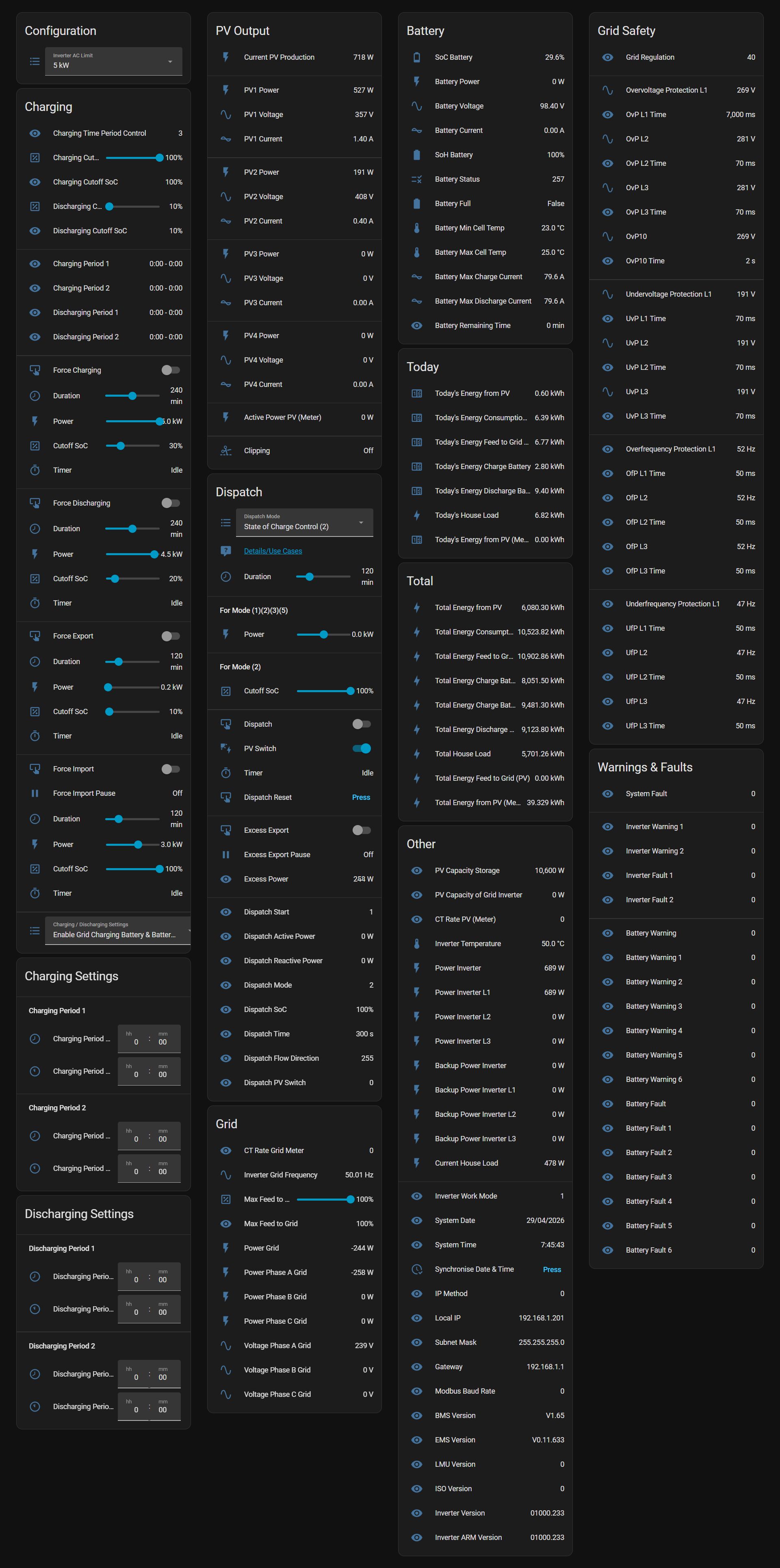
Hello Axel, I don’t think that you produce or consume 200.000 kWh ( = 200MWh ) per day ( see the “Today”s entries in your picture ). There seems to be a miscalculation in your ( and my ) configuration with kWh.
Ciao.
Sirko
Hey Sirko,
are you saying you don’t trust me? 🤣
Yeah, that’s messed up – but the calculation is actually fine. It’s the cloud update that has messed this up and it will solve itself eventually. The root cause is that the “Today” entries are calculated from the “Total” values – and some of these jumped to “zero” (or “unavailable”) and back multiple times over the weekend.
Nothing to worry about – I’ll take a new screenshot soon anyway, once I’ve finished testing some new functionality.
Cheers,
Axel
Hi Axel, “don’t trust” is the wrong wording. It would be more correct to say that I would be annoyed because I can’t achieve such values with my PV system. 90kWh was my highest daily production so far 😉
One more question about the diagram: With “legend_value: true” I can also display the current value for PV production in the legend. Can I also somehow put the daily total (i.e. a completely different value) behind it? “5.6kW / 25.3kWh”
Thanks.
Sirko
Sirko,
that is a very good question and I have no clue. I’m not exactly an experienced HA user and have even less knowledge about ApexCharts. You might find an answer or help on GitHub: https://github.com/RomRider/apexcharts-card.
If you can find some configuration options for the chart that might be useful for others let me know and I will add it to my template.
Feel free to contact me directly via mail 😉
Cheers,
Axel
This has been a lifesaver, especially given the recent API issues at Alpha – switched over easily, thank you!
Hi Reece, thanks 😉 I’ll be releasing a new version soon but am delayed with testing because of the ongoing backend issues.
You made my day Axel, I got the modbus working on my Smile5 using a PE11 RS485-UTP module thanks to your yaml files.
But I’m stuck on adding extra sensors. How do I convert eg the hex address 001AH (26 decimal) from the AlphaESS register catalog to your ‘1052’ value in your yaml? I want to add Total PV Power (I have an extra PV meter for second old PV installation), and think I can do with address 052DH (Total PV power).
Might be stupid data conversion question, but I’ve got no clue where to look.
Regards, Tom (KermtStroomt).
Hey Tom, that’s great to hear 😉
Yes, you can use any Hex to Dec converter, I’m using this one: https://www.rapidtables.com/convert/number/hex-to-decimal.html. So, 052DH would be 1325 decimal. I’m not sure about your “1052” example, that is 041CH (Inverter Grid Frequency), not 001AH (Frequent(Grid)). I’m also confused about 052DH, I don’t see that register in my AlphaESS-ModbusRegisterParameterList.pdf. Shout, if I can help, preferrable via projects@hillviewlodge.ie.
I am delighted to hear that the PE11 is working for you and would love to hear details on how to set this up. I have the same device here, unused in a drawer. When I started looking into Modbus end of last year I thought I needed one, before actually realising that my inverter supported Modbus TCP.
Cheers,
Axel
Hi Axel,
great work and result. Pefectly structured code and documentation is first class. Although I had to rewrite some automations that were based on the AlphaEss Cloud integration I am now fully independent when the Cloud API is not working like last week for about 6 days.
A big thank you for this. One question I still have to you: It seems you have implemented almost every useful field from the Modubus Doc from Alpha inluding charging switches and charging times, why did you not include the same set of fields for discharging. Maybe I did not find them in either the code or the dashboard ?
Thanks again and best regards
Juergen
Hi Juergen,
thank you very much, glad you like it 😉
Regarding the Discharging Setting: I didn’t add the setting (yet) because I actually never use them and I never had anyone ask for them before. Is that something that would be of use to you? I wouldn’t mind adding them, esp. after the recent mess with the cloud and me toying with the idea to block the inverter from Internet access all together.
Cheers,
Axel
Hi Axel,
Ja die Parameter für discharging wären sehr nützlich. Ich habe es selbst mal versucht, bin aber nicht erfolgreich gewesen.
Gruß
Jürgen
Hi Juergen,
let’s use mail (projects@hillviewlodge.ie) for the conversation in German – if you don’t mind 😉
Thanks,
Axel
Is there any way to calculate the power used by the non essential side of the inverter it’s a smile 5.
Thank you
Hi Pieter,
I’m not sure I understand what you mean – what is the “non essential side”?
Cheers,
Axel
We have the gyser and oven/stove connected between the inverter and the grid ct (we are not allowed to feed solar back to the grid) the CT is to stop feeding to the grid. But the inverter can still supply solar to the non essential side in my case the gyser and oven/stove.
I’m trying to figure out what the difference between “Inverter_Power_Total” and “Inverter_Backup_Power_Total”
Hi Pieter,
I’ll send you an email in a minute.
Cheers,
Axel
Hi Axel,
first of all THANK YOU a lot for this work and Project. You have saved me much time to get this working on my own :). One question – have you managed to calculate the “total income”? I get mad of this. I’m pretty shure my values are incorrect . 🙁
Hi Christoph,
thanks, glad it’s working for you. I haven’t looked into anything “profit” related, not sure if I will bother – but I’m happy to help if I can. If you’d like to continue the conversation in German I’d prefer if we could use email via projects@hillviewlodge.ie.
Cheers,
Axel
Thanks for this, it’s a great help since AlphaESS messed up the existing integration I’ve been using with their recent update. It’s taken me a long time to get this working on a Smile5 AL5002 without TCP, turns out my system has been set from the factory with a baudrate of 115200 not 9600 that I’ve been using to try make this work, I also connected pin3 (white/green) to the RS485 ground connection which has improved the signal on my system.
There’s a small mistake in your serial/RTU config example, the parity needs to be set with a capital N not lower case or it throws up an error in Home Assistant.
Hey Dan,
thank you very much for that feedback, I will update the website asap. If you don’t mind: which adapter are you using – just for my records?
I also have a contact in Australia who’s just in the process of connecting a Protoss PE11 (RTU > TCP), so I’m hoping to be able to add information about that adapter soon.
Cheers,
Axel
Hi Axel,
It’s the Waveshare USB/RS485 (https://thepihut.com/products/usb-to-2-channel-rs485-industrial-grade-isolated-converter), I’ll be switching to RS485 to ethernet now that I have it working on the USB version, I bought both while trying to get this to work but I accidently fried the Ethernet module in the process so I’ll need to buy another. I’ll report back if I get it working in case it helps anyone else out, I found some posts online with people struggling to get Modbus working on the early hardware version Smile5’s so it might simply be the different Baud rate causing the issue. I was experimenting with Alpha2MQTT which tries a selection of Baud rates automatically which is also how I found out about the ground connection on pin3, it didn’t work at all until I connected that.
Hi Dan,
thanks for these details, might be handy for others. You’re not planning to use the Protoss by any chance? I have one myself, ordered it before realising that my SMILE5 had Modbus TCP… Lesson learnt 😉
Cheers,
Axel
Hi Axel,
Thank you so much for the wonderful work you do and sharing your knowledge. I bought a HA Green and followed Charles’ instruction to integrate with my AlphaESS SMILE-G3-B5-INV. What I’m trying to do now is to force discharge my excess energy during the evening peak hours. However, my battery is connected to my home router using WiFi and your first prerequisite says it must connect via a LAN port. I have forced discharged my battery previously using my electricity providers (Amber) app but I’m trying to do this independently via HA. Do I need to figure out how to connect my battery via a LAN port first before I do anything? Has anyone else got this working using Wifi?
Thanks,
Mamoon
Hi Mamoon,
I might not have explained that very well I’m afraid: Modbus TCP does work via Wi-Fi, it’s just the AlphaESS Wi-Fi Stick that doesn’t work support that. So if you can’t run a LAN cable you can alternatively use either PowerLAN or a cheap Wi-Fi repeater with LAN port (like the TP-Link TL-WA850RE, very cheap and my preferred option). You can then connect the inverter via LAN port to the repeater and you’re sorted.
Hopefully that’ll help you sorting this bit, if you need any additional information fee free to ping me directly via projects@hillviewlodge.ie.
Cheers,
Axel
Thanks Axel. I’ve ordered one, will let you know how it goes.
Hi Axel, fantastic work!
I am currently using alpha2mqtt, which is working fine, so I know I can read/write to my smile5 ok. My only issue with it is node red which I don’t use for anything else, and really don’t want to learn.
Sadly my smile5 does not support TCP, so I have got a Waveshare RS485 to POE ETH to try.
All is working fine, I can see all the data in HA, except none of the write commands work, which I’m guessing is a setting in the Waveshare that I’ve got wrong.
I appreciate that you don’t have this unit, but am wondering if anyone else has got it working ok and can help with settings?
Hi John, thank you 😉
Just to clarify: you’re not using my integration to write, but Node Red? I’m asking because I did make some changes in relation to how I’m writing values, these changes were required for Modbus RTU users. It has to do with the two methods to write to registers, “Write Single Register” and “Write Data Register”. Daniel of Aplha2MQTT mentions these methods to and I have switched to “Write Data Register” because it’s working for both Modbus TCP and Modbus RTU. I have a contact who’s in the middle of connecting his system via the Protoss PE11, should be pretty similar to the Waveshare converter.
Feel free to contact me directly via projects@hillviewlodge.ie, easier than using the commenting functionality 😉
Cheers,
Axel
In the meantime I managed to install the package and I am using it on a daily basis, but only the monitoring part.
I am looking for some kind of documentation what the respective sensors and especially the buttons/input entities do.
I did scroll through the ModBus documentation but did not manage to really get behind which is what.
Is there some documentation how to use the entities (functionality of “charging/discharging setting”, the time slots, “excess export” “excess export pause”, throttle/load buttons) and the correlation/dependencies between them?
Hi Marius,
feel free to reach out via email (projects@hillviewlodge.ie) and I will try to explain some of these settings and automations. You won’t find anything about that stuff in the AlphaESS or Modbus documentation, because I created them.
I thought most would be self explaining (since they’re replication the AlphaESS App/WebUI functionality – like “Charging / Discharging Setting” and the corresponding time slots.
“Excess Export” (and “Excess Export Pause” – which is just a helper and is not to be used by users) is probably not relevant for German users, afaik you guys don’t get paid a lot for feeding into the grid. Details can be found on my website:
Enabling “Excess Export” will change the inverter’s load serving priority, the default being the sequence: House Load > Charge Battery > Export to Grid. Once enabled the inverter will prioritise feed-in, the sequence will be: House Load > Export to Grid > Charge Battery.
Throttle Charge – as the name says – charges the batteries from the grid at a throttled rate, in my YAML at 2kW instead of the the full 5kW.
Cheers,
Axel
Hi Axel,
I just want to share with the community that I got Modbus working on my AlphaESS SMILE-G3-B5-INV but I couldn’t have done it without you. Thank you so much for all your support and guidance over the last 2 weeks. You are incredibly knowledgeable and very patient when it comes to dealing with novices like me.
I’m truly grateful.
Cheers,
Mamoon
Hey Mamoon,
thanks for your kind words – I’m delighted that it’s working for you 😉
Cheers,
Axel
Hi.
I am using already for some time forced charging in same way as you do but despite setting 100% SOC inverter stops actually on 99.2% always. Have you experienced the same or your one is fully charging to 100%?
Also I found out that if battery is charged sooner (SOC reached) than set charge time elapsed, then inverter stays in this charging mode and prevents consuming loads from battery.
Hi Zdenek,
yes, I have heard from others that the system might not charge up to 100%. I never saw that happening on my SMILE5, it always charged to 100% without problems. I have recently swapped to a SMILE-G3-S5 with more battery capacity and I’m only charging 70% now to reduce/eliminate clipping. The guys that reported the problem you are seeing seem to have “fixed” this by setting register 2182 to a higher value than 250 (which is 100%). They said it was working fine once setting the register to 251. Maybe worth a try if it bothers you 😉
I’m also aware of the fact that the system stays in charging mode until the set time is elapsed – that’s bad design but it’s fine for me: since I’m charging at the cheapest night rate I actually prefer that the system stays in charge mode. That way the house loads are served by the cheap night rate until the time is elapsed and it’s not using the battery.
What’s far worse is that it does the same when force discharging. I’m force discharging down to 20% SoC at night, before my cheap rate starts. If 20% is reached before the time’s elapsed the house loads are served by the grid – and that is at the expensive rate, because the cheap rate hasn’t started yet. I’m avoiding that by using a “helper” automation that monitors the SoC and stops the dispatch mode once 20% is reached.
Cheers,
Axel
Hi Axel. Thanks for the huge amount of work you have done on this, over one year. I was impressed by the huge list of versions at the head of the .yaml, and that there were even some comments in it! 🙂
I must be getting a little too old for this stuff now, because I couldn’t work out how to change the view?
I click the Overview’s pencil to edit, it brings up an “Edit Dashboard” dialog,
but it only lists stuff about areas and hiding energy. Nothing about adding a view.
P.S. Some of the version strings seem to be parsed incorrectly. e.g.:
BMS Version 1,114 (instead of V11.14)
EMS Version Normalised Vunknown.unknown.unknown (instead of V0.11.07T)
______________________________________
Nigel, Sydney, Australia.
HAcore 2024.11.1, AlphaESS SMILE5
Hi Nigel,
thank you very much – I know that feeling of getting too old for all this 😂
I’ll respond via email if you don’t mind.
Cheers,
Axel
Hi Axel
I came across this while trying to find something for my smile-b5, it’s working great for the most part! Thanks.
However, I’ve noticed that the majority of the values are incorrect for systems that have a seperate solar system (I got my battery installed seperately from the solar system).
So values like all the PV inputs are 0, the house load is not calculated correctly and feed in is a negative number.
Is there any quick config changes I can make to correct this?
Hi Evie,
yes, some things are different for AC-couple systems, some information doesn’t exist and some can be found in different places. Also some values are off by factor 10. For these open my integration_alpha_ess.yaml and search for “B3”, you will find 6 occurrences with alternative multipliers in the comment.
The PV input per string can’t be read on AC-coupled systems, but the combined output is available, see Active Power PV Meter (sensor.alphaess_active_power_pv_meter) in the “Other” card. I’ve also added two additional sensors (AlphaESS_Total_Energy_From_PV_Meter & alphaess_todays_energy_from_pv_meter), you’ll have to add them manually to your view.
Hope this is helpful, feel free to contact me directly via projects@hillviewlodge,ie.
Cheers,
Axel
Hey Axel,
first of all thank you big time for your amazing work. I stumbled upon it when AlphaESS cloud was offline for a few days during last fall.
Recently they changed the battery grid charging / discharging UI in the official website and app to support more than 2 time windows each incl. cutoff SoC. I feel like the old registers for these values don´t work anymore but of course there is no newmodbus documentation from AlphaEss. Do you know anything about it?
Regards
Ron
Hey Ron,
thank you very much <3 I did notice a significant increase of queries during and after the cloud mess. I was starting to worry that it might be too time consuming but thankfully it has calmed down a bit ;)
I did indeed notice the new charging/discharging functionality and the additional time periods but I can confirm that the old Modbus registers are still working - at least for me. I haven't received any reports about them not working - but then I believe that only newer models have received the new functionality and old systems didn't. I can see that my old system (SMILE5 Gen2) still shows only 2 charging periods while my new G3-S5 shows the option for 6. I am still using the 2 Modbus periods register sets (since I've automated charging depending on solar forecast), all new periods in my App/WebUI are disabled.
Besides that I'm assuming that the new charging periods are stored in the cloud only and not locally on the inverter anymore (which could be easily tested by disconnecting the system from the Internet over night). Regarding any updated Modbus documentation: I was told that the AlphaESS guy who was tasked with Modbus enhancements and documentation has left the company and that that was the end of it - for now :(
Feel free to contact me directly via projects@hillviewlodge.ie – you can even contact me in German, according to your IP you’re located not too far from my hometown 😉
Cheers,
Axel
Excellent integration. Installation was straight forward and works perfectly since couple of weeks. Now I tried to add myPV ELWA2 AC to my setup and run into trouble connecting the new device to my AlphaESS Smile Inverter. Solution: Using the HA Modbus-Proxy allowed me to connect both HA-AlphaESS integration and myPV ELWA2. Perhaps this tip will help others as well.
Regards – Raffael
Hi Raffael,
thank you for the positive feedback 😉
Cheers,
Axel
Hi Axel,
I really appreciate your implementation and it works soo good, thanks for all that.
My plan is to use the whole system offline and I will use your modbus integration within Home Assistant to grab data from the inverter. Works perfectly! <3
Currently I'm facing an issue and I don't know if you can handle this via modbus as well:
I also own an AlphaESS EV Wallbox (EVC11) and it seems that this stupid wallbox is connected directly via LAN to the converter and can only work with internet connection.
I have to use the APP to change the settings of the wallbox (charge mode, start / stop). Obvoiusly the connection to the wallbox fails once I put the system offline and it seems that I cannot change the settings there.
I guess the communication between the inverter and the wallbox is the problem and I'm not sure how to use the wallbox wihtout internet.
Do you have any experience with this setup or any idea how to use the system completely offline?
I also spent time to use EVCC but my Wallbox refuses connections from "external" sources. It only accepts commands from AlphaESS inverter. I got intouch with AlphaESS and they told me that this behaviour is by design.
So long story short: is there any possibility to use modbus to have a basic control over the wallbox as well?
Thanks and best greetings from Germany,
Martin
Hi Martin,
great to hear that it’s working well for you 😉
Unfortunately I don’t have any experience with the EVC11 – thankfully I don’t have an AlphaESS EV charger (mine is a myenergi zappi). You might be able to find additional details about EVC11 offline control on the German AlphaESS forum (https://www.storion4you.de/), it seems like that charger is pretty popular in Germany.
Another thing: check your warranty conditions regarding taking the system offline for extended periods: I recently swapped from a SMILE5 Gen2 to a G3-S5, the G3 series comes with a 10 year warranty but it reduces to 3 years if not connected to their cloud for some time.
Cheers,
Axel
PS: feel free to contact me directly – even in German – via projects@hillviewlodge.ie 😉
5 minutes install … after I figured this out:
Our SMILE-T10-HV-INV was delivered today – event the solar panels are not yet on the roof I of course started to set up this integration. I struggeled because I have another modbus client – a lambda WP that is already controled via modbus from HA.
I figured I if I copy both yaml files together below one modbus tag it worked. After that it took 5 minutes to setup.
I am really impressed by the detailed integration. Really nice!
Maybe this helps someone along the way.
Thanks Christian, glad you like it 😉
Cheers,
Axel
To me it looks like the battery load value in the Daily Power Diagram is always showing doubled numbers. In your example screenshot as well as in my HA setup it has 9 or 10 kW at 100% even though the AlphaESS app displays a value of 4.5-5 kW with which the battery gets loaded. Maybe I have the wrong understanding, but to me this looks like a bug. What do you think?
I believe you’re mixing up two different things: the battery chart in the Daily Power Diagram is displayed in percent (the scale from 0% to 100% on the right side of the diagram) and not in kW. It’s doing exactly the same in the AlphaESS Power Diagram in both App and WebUI.
Depends 😉 To me it looks like the AlphaESS app addresses both scales at once – battery percentage (right) and its loading/unloading in kW (left). I checked the kW today 1-1 against the diagram and it sounds correct besides the percentage value.
Hey! First off, huge thanks for the awesome work you’re doing — really appreciate it!
Quick question: I’m using a SMILE-T10-HV-INV inverter together with the SMILE-G3-EVCT11/S wallbox.
Support told me it’s not possible to control the wallbox through the inverter’s Modbus interface.
Do you happen to have any experience with that?
Hiya David,
thankfully I don’t have an AlphaESS wallbox myself, so unfortunately I have zero experience with that. I have a myenergi zappi myself. You should ask on the German AlphaESS forum (https://www.storion4you.de/), hopefully someone there is able to help.
Cheers,
Axel
Hello Axel, just installed your yaml.files. All is working very well !
I use a SMILE-G3-T10-INV 18,2 Kwh.
Now the theory of your automations, it is all a little dark to me.
I will dive into that en study them thoroughly.
I would appreciate if you explaine some things more, or is that too much to ask ?
Thank you very much for all your nice work !!!
Piet Spoelstra, the Netherlands
Hey Piet,
great to hear that it’s working well for you 😉 If you have any questions regarding the automations: feel free to contact me directly via projects@hillviewlodge.ie.
Cheers,
Axel
Hi Axel,
Nice work you did there. And thanks for the pdf’s on the MODBUS registers and the explanations on all of it.
Recently, I got an AlphaESS system installed myself (SMILE G3 T10 with 3x SMILE g3 bat 3.8s). Since somewhere in time I used to be a C-programmer I thought, let’s make a C implementation for that MODBUS control. Works fine, I am able to read all information.
My question: did you ever try to turn off the inverter returning power to the grid? I thought setting register 0x0800 to 0 (MAX Feed into grid percentage) would do the job but that does not seem to have any effect.
Jaco Melse, The Netherlands
Hi Jaco,
I tested setting register 0x0800 to 0 in the past, it worked fine and grid export completely stopped – but that was on my old system (SMILE5 Gen2). I haven’t tested it on the G3-S5 but might get a chance tomorrow. Feel free to contact me directly via projects@hillviewlodge.ie and I’ll respond there with my findings.
Cheers,
Axel
Hi Axel,
Setting the “AlphaESS Max Feed To Grid” to 0% doesn’t seem to do anything for my SMILE G3 T10 as well. Did you get the chance to test this out?
Thanks!
Hi,
it’s supposed to work fine – tested here on both SMILE5 Gen2 and G3-S5, others are using it on different models. Are you by any chance with an electricity provider that can control your system? Maybe check on the Dutch Tweaker forum, there are a couple of G3-T10 users there (https://gathering.tweakers.net/forum/list_messages/2298732/0).
Cheers,
Axel
Hello Axel, coincidentally, I also use a Myenergi Zappi charging station. Do you have any special advice or ideas regarding your YAML automations and the AlphaESS inverter? Many thanks from a grateful user of your site.
Hi Piet, I don’t have any special advice since everyone’s requirements are different. It all depends on what you’re trying to achieve. As mentioned last time, if you’d like to discuss anything further please contact me via email (projects@hillviewlodge.ie), let’s not use the commenting function on my website 😉
Hi
I’ve done a lot of Modbus on my HA + Alpha, so fairly switched on.
I’ve just got a Zappi for my EV, and I want to be able to stop the battery discharging when the Zappi is charging.
Have you any ideas how to do that? Is it as simple as controlling “Dispatch start” 0x880H, setting 0 for disable, and 1 to re-enable?
I can’t see much documentation on the detail on these specific registers.
Thanks
Hi Mike,
I haven’t done it myself but I can see two ways straight away. You can set the AlphaESS battery into charging mode with an SoC below the current SoC (via the normal Charging Periods), or you can set the Dispatch Mode to disable any battery charging/discharging: 0x0880 = 1, 0x0881 = 32000, 0x0886 = 250, 0x0887 = “x” seconds (duration), 0x0885 = 2 – 0x0887 can be re-written before the time expires to keep it going until you stop it. That’s very similar to my AlphaESS_Excess_Export automation.
Feel free to contact me directly via projects@hillviewlodge.ie if you want to discuss further.
Cheers,
Axel
Is it possible to limit export or feed-in through Home Assistant when feed-in prices are negative?
Currently, I’m only interested in the inverter with solar panels. Battery is for later.
Hi Jonathan,
yes, sure, you can even do that via the Wi-Fi Configuration in the App – but much easier via HA by setting “AlphaESS Max Feed To Grid” to 0%.
Feel free to contact me directly via projects@hillviewlodge.ie if you have further questions.
Cheers,
Axel
Hi Axel
Fantastic integration. Thank you you have helped me solve some issues I was having. Very much appreciated.
I am having a couple of issues with the excess export function I was hoping to ask your advice on:
1. The Excess Export function seems to ignore the max-feed-to-grid setting. I’ve noticed when the batteries are charged the system will export above the max-feed-to-grid limit (e.g. 15 kW/h). Is there a setting I need to change to fix this?
2. The Export Excess function seems to reset and turn off after a period of time. Is this normal? I want to have this setting on so to priorities the grid each morning.
My setup: I have 20 kW solar panels that produce excess power, 2 x Smile G3-S5 inverer/batteries and can feed in to the grid at good feed-in rates up to 10 kW per hour. Like you I am trying to delay battery charing to maximise the grid feed in until excess power exists above the feed-in kW limit. I have the max-feed-to-grid set correctly. I’m often remote to the location and rely upon home assistant to manage the house.
Thank you
Cam
Hi Cam,
thanks for your feedback, always great to hear that things are working 😉
I’ll respond to your questions via email, I find the commenting functionality not ideal for a proper conversation.
Cheers,
Axel
I love the project. From a bit techy to tech savyyyyyy.
Either way, what I am missing, I am in VPP control, Dutch Energy Supplier; however, I think I can achieve more. Either way; charging and dispatching works perfect as expected. I just received my HA Green.
I would like to have some automation:
1 inverter for PV and one for the AlphaESS system. They are not connected, but do measure the PV installation.
So, I would want during the day, if PV export, rather first fill battery, and during peak hours (can we get a automatic read somewhere of EPEX pricing?) to dispatch to 15% of battery. This should roughly (over last 4 weeks) give me 6 bucks per day. I understand that under VPP control they could give a later API command control to overwrite, but that is ok. Start simple first.
Where would i do this?
Hi Roelant,
I’m not sure I fully understand what you’re asking for – but: there is an AlphaESS_Excess_Export automation to prioritise grid export over battery charging and there is an AlphaESS_Force_Discharge automation to dispatch the the content of the battery.
Hope this answers your questions, if not please contact me via projects@hillviewlodge.ie.
Cheers,
Axel
Hi Axel,
Working great because of your instructions but I’m not that technical. The only thing that I did not manage to get right is getting the charge now to 10KW instead of 5. Could you maybe give some guidance here what values I need to fill in?
Cheers,
Niek
Hoi Niek,
great to hear that it’s working for you and I’m happy to explain how to adjust “AlphaESS_Charging_Now” to meet your requirements. It depends on a couple of factors and might require a “proper” conversation 😉 It would be great if you could contact me via projects@hillviewlodge.ie, it’s easier to explain via mail.
Thanks,
Axel
Hi Axel,
Thank you for this great resource. I have been using it mainly to monitor the battery trough HA. I recently stopped being a battery provider for a VPP and now want to start discharging myself. I used to click the discharge button and the battery would start discharging, but after upgrading from version 2.x to 7.0 this button seems unresponsive. The dispatch does not start when trying clicking the Charging Now or Force Discharge. When I click the Throttle Charge however I see the Dispatch mode go to 2 and the active power change.
I have checked the yaml and I can’t seem to find why it wont work with Charge now and Force Dischage, but it does with Throttle Charge.
I have used the “default” file without modifications to make the troubleshooting easier.
Do you have any pointers for me?
Kind regards,
Pascal
Hey Pascal,
I have an idea: did you create copies from input controls (like input_buttons) from my provided alphaess_view.yaml into you own view?
In version 2.5 I tidied up the naming:
# 2.5 2024-05-24 Replaced “Alpha ESS*” and “Alpha_ESS*” with “AlphaESS*”
So if you copied e.g. the input_button alpha_ess_helper_charging_now this copy will not work anymore, the the trigger in newer version of Alpha_ESS_Charging_Now (now AlphaESS_Charging_Now) is referencing input_button.alphaess_helper_charging_now.
Hopefully that’s the problem 😉
Cheers,
Axel
Thanks for this, going to be trying this soon. I’d kill for you to make a YouTube video about this going over the steps and showing how to adapt it to personal needs, as modbus is a bit daunting for a noobie like me. Given how popular alpha ess systems are starting to get over here, you’d probably be helping a lot of people.
Hi Bart,
I understand that it might be a bit technical but don’t worry too much, it’ll work fine. Adapting it to personal needs is a different story though, it depends on the individual: I like it plain and simple and automated as much as possible and others like it all singing, all dancing, with bells and whistles – because they like looking at the dashboard all day 😉
Just reach out via mail, I’m happy to help – I’ve even done remote control sessions with one of my contacts. For starters, here’s a video I recorded showing how to add my provided HA view to the dashboard: https://www.youtube.com/watch?v=Zu3FVMMU7Kc
Btw: I have one contact, a retired mid-70s general practitioner, a complete amateur – and he managed to implement it, practically by himself 😉
Cheers,
Axel
is there a way to check if modbus commands are received and executed by the alphaESS? I have set upped the integration and can now see the entity sensors, but the alpha does not seem to listen to the charge and discharge commands
There are known issue with some older models (SMILE5 Gen1 & T10). When you’re running dispatch commands, can you see the relevant registers changing?
if i press AlphaESS Load Following I don’t see the dispatch mode changing. (it stays 2 on my Smile G3 T10).
my battert is on VPP. does tat cancels out all modbus commands maybe?
Yes, if you are on VPP you might not be able to overwrite settings since they are managed externally.
Where do I find the helper definitions for
input_select.alphaess_helper_inverter_ac_limit
sensor.alphaess_clipping
sensor.alphaess_dispatch_reactive_power
?
They seem to be not included in the yaml.
Line 1247: input_select.alphaess_helper_inverter_ac_limit (this is a helper)
Line 2404: sensor.alphaess_clipping (this is a template sensor)
Line 1135: sensor.alphaess_dispatch_reactive_power (this is a sensor)
The problem (as almost always) sits in front of the keyboard.
I created a backup folder to store the old configuration – but forgot to rename the file, so Homeassistant tried to load both (the old and the new) yaml file.
Well, that surely cannot end well. m(
I’m struggling a bit getting the values in the entities. If I’m using https://github.com/snitzelweck92/homeassistant_alphaess_modbus_tcp everything works fine. I see the major difference is that the adress values are in Hex. In decimal it works fine. In hex I don’t get the values.
Is there any workaround? Thanks!!!
Hi, that’s the first time I’m hearing that, are you using my provided dashboard view and are you suing an up-to-date HA version? Please contact me via projects@hillviewlodge.ie, might be easier for troubleshooting.
Hi Axel,
Thanks for the awesome work on this. Ive been following it for some time, but my older SMILE5 wasnt open to tcp. As a result Ive been using the work of various people to good effect including Alpha2MQTT, Charles Gillanders and Dehsgr node red integrations.
That all changed recently when the old inverter failed and was replaced with the same (but later hardware)
Ive revisited your work and within 5 minutes had it up and running!
Great stuff and now I can start to clean out the old code and consolidate it with yours.
One change I made with my graphing (original code, not yours – yet) was to modify the display to show PV1 + PV2 + PPV as its interesting to see how much each string is creating at different times of the day.
But anyway – love your work, keep it up!
Hi Spooky,
great to hear that the migration went very smooth, good stuff. Did you get swapped to a G3-S5?
I do host an extended Power Diagram (https://projects.hillviewlodge.ie/_alphaess/power_diagram_extended.yaml) including a diagram for the string details, a 3 day diagram and some others but it’s not linked on the website. You can see the additional diagrams in the screenshot on the website. Maybe I should add the URLs for both versions.
PS: I’ve only yesterday decided to start posting future updates about changes/enhancements in the AlphaESS Facebook Group, that’s easier than manually checking for file changes every couple of weeks.
Cheers,
Axel
Hi,
I have installed HA on my PI4 which went well.
However, I don’t have a “config” folder under the “homeassistant” folder.
So I created the “packages” folder under “homeassistant”, configured the “secrets” file and restarted HA.
I see a lot of parameters in the default dashboard but all sensors show “not available”.
I tested the modbus connection from my Windows pc with positive result. The PI4 is in the same network.
ComputerName : xxx.xxx.xxx.xxx
RemoteAddress : xxx.xxx.xxx.xxx
RemotePort : 502
InterfaceAlias : vEthernet (New Virtual Switch)
SourceAddress : xxx.xxx.xxx.xxx
TcpTestSucceeded : True
I added the IP of the PI4 in the secrets file with and without quotes but no difference.
What am I doing wrong ?
Thx in advance.
Hi Jos,
is it possible that you used something like the “File editor” add-on instead of “Samba” (and mapping the \\homeassistant\config share)? I believe the “config” folder is not visible in the “File editor” – you are looking at /config by default.
Feel free to contact me via projects@hillviewlodge.ie, that’ll be easier for further troubleshooting.
Cheers,
Axel
In the ‘integration_alpha_ess.yaml’ file the dispatch mode address is included as 0x885, but as far as the documentation goes it should be 0x727.
Thanks
You are mixing up the “Household System (Only applicable to HHE MEC)” section and the “Household Power Dispatch” section.
Ok, thanks. Both parameters report ‘0’ but the battery is behaving as described for ‘Load following’. Any idea what that means?
Not really, if all Dispatch related parameters are “0” – which means no Dispatch Mode is active. Could it be a VPP provider controlling your system?
No, I’m planning to but have not done it yet.
Dear Axel,
I followed your instruction till point 9 and i get “Integration error: packages – Integration ‘packages’ not found.”
Even in my Home Assistant Installation i dont have the config folder. So I had to create it.
Version of HA: 2025.8.3
Thanks for your reply 🙂
best regards
Ronny
Hi Ronny,
I suspect you mapped \\homeassistant\config and therefore you don’t see the config folder. Can you take a screenshot of your mapped drive and send it to projects@hillviewlodge.ie so I can have a look? Also, feel free to switch to German in your email 😉
Cheers,
Axel
Hi Axel,
Implemented the integration on a SMILE-S6-HV-INV. The maximum output of this inverter is 6kW. However the configuration options allow only 5kW or 10kW not 6kW. Are you able to add that in your integration yaml?
Hi Leo,
done, please take a fresh copy of integration_alpha_ess.yaml and reload the input selects.
Cheers,
Axel
Hi I’ve managed to hook this into my Smile B3. It did catch me out with the baud rate as the default on my PE11 was 115200 instead of 9600 the issue I have though is some of the figures it’s reporting are a bit out. They aren’t wrong but are out. For example the Current house load is showing as 63,831 W but in the alpha app it’s showing 638W the Active Power PV Meter is spot on. Also the battery power in HA was showing -576W but in the app was showing it was charging and was 576W (this one might settle as I’ve just hit 100% charged so I think it might be a slight red herring but when I look at the graph which I’ve configured it’s showing a battery level at 9kW but I only have a 5.50kW usable capacity.
It might be me but I just want to check I haven’t got anything wrong. It’s feeding back some fantastic data and will massively help me achieve what I need to but just want to make sure the data is correct.
Hi Andy,
yes, the Modbus register sensors of the B3 require some adjustments. Open the integration_alpha_ess.yaml, search for all B3 occurrences and change the “scale:” values to the ones specified in the comments. Save the edited file and reload the Modbus YAML configuration (under Developer tools).
Cheers,
Axel
Hi,
thank you for this integration. It’s really nice to have a way to get the values out of a SMILE-T10-HV-INV via Modbus, which does not require any external cloud services.
My system also contains a second inverter (a Sungrow SG10.17RT), which unfortunately does not provide reliable modbus data. While your integration is properly displaying the solar power of the string attached to the primary AlphaESS inverter, I don’t see the data of the other strings attached to the external inverter. But other values like “Feed to Grid” are correct and contain the power of full system.
In the AlphaESS cloud view I do see the full aggregated power of all strings. And since some days there is a new small hamburger menu showing a tooltip with five entries: PV1, PV2, PV3, PV4 and PV_DC. The values of PV1 to PV4 directly map to your “PV1 Power” to “PV4 Power” entiies. But I didn’t found any entity representing the value of “PV_DC”, which looks like the exact value I’m interested in. I’m currently running version 7.3 of your integration (had trouble with updating to 7.7, so stayed for now). Have you added that entity by any chance in a newer version of could you give me some hints how to get the information from the AlphaESS modbus?
Thank you!
Best regards,
Tobias
Hi Tobias,
that entity should be available in your version, it’s “Active Power PV (Meter)” in the “Other” card. It has been moved to the “PV Output” card in the current version and has also been added to the “Current PV Production” formula.
I’m sorry to hear that you had an issue with upgrading, feel free to contact me via email and also feel free to write in German 😉 I might be able to help with the upgrade, I know a lot has changed recently, esp. 8.1 was big one. The 8.1 changes were on my to-do list for some time and I’m glad it’s done now, so hopefully there won’t be any big updates in the near future.
Cheers,
Axel
Thank you Axel! The latest changes on version 8.x, esp. the inclusion of the “Active Power PV (Meter)” in the “Current PV Production” is a game changer! I updated to version 8.5 and this time, the update of the “alphaess_view.yaml” worked flawlessly. This is a really great integration! (Now, I need to figure out how to import/correct historical data).
Best regards,
Tobias
Hi Tobias,
just an FYI: 8.6 was released earlier today. File integration_alpha_ess.yaml is the only one affected, no updated view.
Cheers,
Axel
Looks like the “Total Energy from PV (Meter)” and “Today’s Energy from PV (Meter)” do not contain the energy portion of the “PV Output”, but only PV energy of the primary inverter. As a result, the HA energy view displays a 0 kWh for home in the distribution graphic. The graphic also claims, I feed more power to the grid than what came from PV (due to the missing “PV Output” portion).
Another thing is, that the “Active Power PV (Meter)” seems to be constant at “11 W” when it should be zero, e.g. at night. The values in the AlphaESS cloud view are zero. At daylight, the value seems to be correct though.
Oh, I think I need to add both, “Total Energy from PV” and “Total Energy from PV (Meter)” to the energy chart configuration as PV generators. Except the “11 W” glitch, values look more reasonable then.
Axel.
How much success have you had with curtailing Alphaess to 100%. Im on a beta program with someone so they can develop an Energy management system. The main issue is it will not curtail. The commands are being sent in Home assistant to the correct register but we feel they are either not acted on or are either being rejected or lost. Im asking you as you may know if anyone else is having this issue or if its even possible. Previously , my Energy Provider (Amber) failed to curtail even though they said it was working. The Alpha App tells a different story. Im sorry i cant discuss many aspects of the Beta program as im on a NDA agreement. Smile S5.
Thanks
Hi Glenn,
is it the Max Feed to Grid setting you’re referring to? It seems like the setting has no effect in AU, someone recently got confirmation from support. There might be another approach if limiting the grid export is what you’re trying to achieve?
Just to clarify: setting Max Feed to Grid to e.g. 0% works perfectly fine in other countries. I’ve tested it here myself. Reaching out to AlphaESS to find out the reasoning for the setting being ignored in AU might be worth it, maybe it’s a mistake… Prior to that you might want to double check that the setting also has zero effect when being configured through the AlphaESS App (under WiFi Configuration).
Cheers,
Axel
Thanks for this great setup. Works fine with my SMILE-G3-T10-INV / SMILE-G3-BAT-3.8S inverter and battery combo to get all the sensor values.
One thing I can’t seem to figure out however. For my battery control script (with optimal state calculation coming from emhass) I basicly need 4 modes for the battery.
1 follow grid (zero import export)
2 forcible charge a fixed amount power
3 forcible discharge a fixed amount of power
4 do nothing (no charging or discharging, keep battery at 0 Watts)=> tried using Force Charge with power 0
I’ve tried creating a script/automation that loops every 30 seconds that sets input_booleans (like input_boolean.alphaess_helper_force_charging) and numbers (like number.alphaess_template_force_charging_power) and switched back input_select.alphaess_helper_dispatch_mode to Normal Mode (5) but I just can’t get it to work with the needed predictability.
Any tips on what I could try to find the right sequence to to set these 4 modes using your inputs and automations?
Thanks in advance.
Hi David,
glad you like it 😉 Regarding you questions/issues: would you mind contacting me via email (projects@hillviewlodge.ie)? I can provide some demo automations or create what you need if you’re able to explain exactly what you’re trying to achieve. This commenting part of my website isn’t great for having a proper conversation…
Cheers,
Axel
email was sent…
Hi, this looks great but before I install and configure, a few probably very stupid questions if I may.
1. I assume the system doesn’t have to be in a dispatch mode? What is it’s normal operating mode … is there a default mode?
i.e. priority
If PV is greater than load
PV to Load
then
PV to bat
then
PV to grid
If PV is less than load
PV + Batt to load
If Load > PV+Batt
PV+Batt+Grid to load
2. When dispatch is turned on I assume it auto turns off at the end of the period?
3. What’s the difference between using force discharging and force charging versus just setting set the dispatch modes and turning dispatch on?
4. Is dispatch mode 6 the same as dispatch mode 2 but at the set inverter ac limit and to 100% SoC?
Many thanks
Hi Mike,
no such thing as stupid questions 😉 I’ll respond via mail if you don’t mind, this comment section isn’t great for that type of discussion…
Cheers,
Axel
In need of some guidance 🙁
My Protoss PE11-H has finally arrived.
I have a SMILE5-INV AL5002xxxx series.
I’ve wired :
RS485/CAN port pin4 to the PE11 connection 5 (b)
RS485/CAN port pin5 to the PE11 connection 7(a)
PE11-H config:
set serial port 9600,8,N,1, Protocol Modbus
communications netp set to tcp server port 8899
SMILE5 config:
this has NO Modules Modbus menu item. … is there anything I need to configure here?
So .. my questions are:- have I set everything up correctly and should I expect to see anything happening over the serial port on the PE11 before I go ahead and start configuring HA?
Many thanks.
I’ll send some infos via mail…
Many many thanks Axel! Now up and running!
Especially grateful what with AlphaESS cloud cert expiring!
Time to trash my old Automations and set up ones which will actually be able to do what I need.
Do you have a beer/Guinness fund I can contribute to?
Great work.
Good stuff, great to hear that it’s up and running now.
I’ll take a Guinness or two next time you’re passing Kinvara 😂
Dear Axel,
Thank you for your work and the awesome integration you have created!
I recently had the problem of an increasing SOC gap between the individual battery units. This caused the entire system to freeze.
Solved by a restart. This SOC gap and freeze could happen again if I don’t regularly charge the battery to 100%.
The tech guys at AlphaESS showed me a list of the SOC of every individual battery unit.
Smile G3-T10 12×3,8 kWh, the Netherlands
Question: can this information (SOC per battery unit) be retrieved through modbus?
Hi Rein,
thanks, glad you like it 😉
I saw your post on the Tweakers forum… I only charge the battery to 100% every 6-8 weeks-ish, never had an issue. I don’t know if it’s possible to read the individual SoCs, never checked. Did you already look through the register list and didn’t find anything? I can have a look later – if I remember. Feel free to drop me an email at projects@hillviewlodge.ie, maybe you can include a screenshot of the list AlphaESS sent you?
Cheers,
Axel
Hi
Home assistant isn’t able to find the entities.
I followed the steps, even tried the B3 entities although I have a G3 inverter.
Could you point me in de wright direction?
I checked if the port was open via windows powershell and it came out true
Thanks
Willem
Hi Willem,
please send me your HA logfile via email – restart HA first to create a clean one.
Cheers,
Axel
Hi Axel
Thanks for the timely reply.
I found the mistake, i confused step 7 and 8 and had not read the config file step.
Thanks for the integration! looks good.
Hi Willem, glad you’ve found the issue and that it’s working now.
Awesome work. This sensor could be a useful addition.
# Total Energy from all PV
– name: AlphaESS Total Energy from all PV
unique_id: AlphaESS_Total_Energy_from_all_PV
slave: 85
address: 0x08D2
data_type: uint32
unit_of_measurement: kWh
device_class: energy
state_class: total_increasing
scan_interval: 60
scale: 0.01
precision: 2
Hi Daniel,
yes and thanks.
Unfortunately that register came with a firmware update and is only available on some models. I’m trying to support as many models as possible. Also, if you’re planning to use it within Excess Export (or a similar automation), make sure to reduce scan_interval to 1.
Cheers,
Axel
Thank you, this is great. I’ve struggled for a week to make it work and I’ve discovered my mistake. If anyone has the same problem: the directory named “packages” is case sensitive. I had named it “Packages” and Home Assistant didn’t find it.
Hi Koen, glad you found the issue 😉
Cheers,
Axel
is there any way to get individual batteries statistics etc temperature soc etc.
Hi Dylan,
I don’t think so, but I’m not sure. I didn’t really look into that, being more into automation and not very interested in data. Have a look at pages 5-8 (0100H-016DH) of the register list, maybe there’s something in there that might be of interest.
Cheers,
Axel
Hi Axel, do you know a way to set a limit on the sensor.alphaess_power_grid for peak shaving? In our country (Belgium), we pay taxes based on the maximum amount we took in one quarter of an hour in the whole month.
I have to use cases:
– charging the AlphaESS on a day with little sun. I use Force Charging and I set a maximum power (number.alphaess_template_force_charging_power), which works fine. However, when there are other appliances using power, the battery keeps charging at the full power I set, so Power Grid is higher than I hoped.
– charging my car. I use the AlphaESS to assist in charging for peak shaving, setting a limit through Load Following (3) to prevent my battery completely emptying itself into the car. However, I would prefer the battery to assist even less when the sun is shining. In this case, Power Grid is lower than I hoped, which means I’ll have to recharge the battery more when the car is charged, but by then the dynamic prices are higher.
–> In both cases, Power Grid provides the information I need to adapt the maximum power in Load Following (3) or State of Charge Control (2). Do you know a way to make it work? Thanks in advance!
Hiya Koen,
sure it can be done, might need a bit of fiddling and lots of testing. Have a look at the Excess Export automation, that’ll give you an idea how to dynamically adjust State of Charge Control (2). You might be able to just duplicate the Excess Export code and adjust to your needs
Cheers,
Axel
Thanks so much Axel, I’m not technical and thought it would be too much but was able to follow your excellent instructions and install on a Raspberry Pi 3. I have just signed up with the new AGL Battery rewards tariff which pays a good price for exports between 5 & 9 pm, is it possible to automate forced export of my battery at 5 pm until only 40% is left? Thanks for any further help, Brett
Hi Brett,
glad to hear that you managed getting it up and running following my instructions. It was my intention to document everything in a way that suits the less technical audience. Forced export shouldn’t be a problem, drop me a line via mail and I’ll send you a demo automation. All I need to know is: time/duration (17:00-21:), SoC (40%) and Power (please provide).
Cheers,
Axel
Thank you very much for this, very useful. Installed this and HA for the first time today, easy to follow and gave me lots more details and control over my battery.
Assuming it is on the newer version of HA, when trying to install power_diagram.yaml, I can’t find “In HA’s Overview select “Edit Dashboard/⋮/Manage Resources/Add Resource””. Turns out it is hidden and I need to enable Advanced mode by clicking on my user name at the bottom left and the Enable Advanced Mode.
Thanks for the heads up, I’ll add the information about Advanced Mode.
Hi Alex
This has opened the door of HA for me, and I appreciate your expertise in helping me move forward.
In my case, I have two Smile S5 inverters at my house, connected via two Ethernet cables, each with a dedicated IP address. I have tested to control them individually with no issues by changing the IP address in the secret YAML file.
I aim to integrate both inverters into HA to enable automation. I’ve tried using ChatGPT to modify the file downloaded from your link, but renaming the two inverters has been tricky for me(or ChatGPT) because of my limited understanding of the logic.
Can you please help with this?
Ken from Australia.
Hi Ken,
I have looked into that before – but never made it further than “looking” 😉 Drop me a mail please and I’ll try to help.
Cheers,
Axel
Hi, I’m new to HA and I’ve used your integration for my Smile 5 system.
When program it to charge the batteries from the grid, its works like a charm. I then do a Charge/Discharge Reset just to make sure that it doesn’t charge again the next night if it is not required.
I normally set my Discharge cutoff SOC to 25%, but when I do the reset it goes to 10%
Maybe I’m missing something, but is there a way to set it to 25% instead of 10% ?
Hi JJ,
how do you do a Charge/Discharge Reset and which version of my YAML are you using? I think it was fixed in version 8.9.
Cheers,
Axel
I see I was using 8.9 but I’ve now updated to the latest version.
I use the Press Reset Charge/Discharge Button and it still resets it to 10% even though I set the slider to 25% on HA.
Sorry, not sure if I ‘m using the correct option / function
JJ, I’m really not clear about which button you’re using, would you mind dropping me a mail with a screenshot?
Hi Axel,
I have Smile5 dc coupled, and am putting a 5kw AC coupled sungrow next month. Should I change the Inverter AC configuration to 10kw or leave at 5 when extra inverter active?
Hi Kev,
you should leave it at 5 kW. The only relevance that setting has is scaling the Force Charging/Discharging and Dispatch Power sliders to match the inverter size plus the Excess Export logic will adjust (if that automation is even relevant to you). So, you could even just “play” with the AC Limit to see if changing it to 10 kW gives you any useful extra.
Cheers,
Axel
Legend,
Is there a fix for load following (mode 3) yet in aus on Smile5? Amber smart shift curtailment works but mode 3 doesn’t seem to do the same thing. I want to disable smart shift altogether but need it for when I have negative feed in.
Hi Kev,
I’m not aware of a fix, but keep in mind that the firmwares/softwares are country specific and esp. in AU some things work different or not at all (even depending on which part of AU you’re in).
Cheers,
Axel
Hi, I have a smile G3-10 with 3 3.8 batteries. Extra capacity is planned.
Took me a while to get things working (IP address in the secrets DOES need to be in quotes).
Looking at the values I get, it’s is clear that quite a few are wrong compared to what I set in the AlphaESS app (get 0 values).
Mostly the values in the ‘Charging’ section are wrong. Compared to the image in the setup explanation, there is no ‘Discharging’ section.
In the ‘Today’ almost all values are 0.
Is there a way to find out which values should be used to correcty read out the BMS (version is 1.44)?
regards
Ludwig
Hi Ludwig,
sorry to hear that you’re having a hard time. I’m assuming your G3-10 is in fact a G3-T10 and I have more than one G3-T10 user without issues.
Anyway, some comments… My secrets contains the IP address without quotes, no problem here. You might want to clarify “the values … are wrong”. The “Discharging” section will appear if you enable the “Charging / Discharging Settings”. The “Today’s” values are calculated from the “Totals” and reset at midnight – so obviously they won’t be right on day one.
If you require further help please contact me directly via mail.
Cheers,
Axel
Hi Axel,
I’ve been using your work for the past few weeks and i am very thankful.
But i am a bit confused on how to set up the default home assistant Energy dashboard with the entities.
I tried some combinations but still i cant seem to get it right.
Could you maybe share which entities you use as your Grid and PV datasource?
Thanks, Felix
Hi Felix,
glad to hear that you like it 😉
I’m using these:
Electricity grid
Grid consumption: sensor.alphaess_total_energy_consumption_from_grid_meter
Return to grid: sensor.alphaess_total_energy_feed_to_grid_meter
Solar Panels
Grid power: sensor.alphaess_power_grid
Home Battery Storage
Energy charged into the battery: sensor.alphaess_total_energy_charge_battery
Energy discharged from the battery: sensor.alphaess_total_energy_discharge_battery
Battery power: sensor.alphaess_power_battery
If you need additional details just drop me a line via mail, easier to share screenshots and other stuff that way. Also, you can write in German there 😉
Cheers,
Axel
Hi Alex
Thank you for your response on facebook. As stated I have the dashboard running and also the Power-Diagram running now. What I am trying to automate.
1. Export hours 5pm to 9pm
2. SoC – I think 20% to start and I can amend later if necessary
3 Power. – See below – I am currently getting 6.5kW to 7.5kW export to grid with the below settings. Not sure if I will get in trouble for exceeding 5kWh.
I have a 5kWh inverter. I thought that export to grid would be 5kWh less consumption. I have a 5kWh Goodwe DC inverter for the panels (purchased without battery) and a 5kWh SMILE5 hybrid AC inverter for the AlphaESS (2×13.3) 26.6kWh batteries. Due to the auto discharge to grid not working on the discharging periods, I have it currently set to AlphaESS Force Discharging ON, cutoff SOC 20%, Duration 240 minutes and Force Discharging set to 5kWh. Max Feed to the Grid. AlphaESS Inverter limit Ac limit =5kW.
I am currently getting 5kWh discharge from battery, 2.23kW Solar Power, 6.22kw Feed-In and 946W Load. It was up to 7.5kWh Feed-In. Maybe getting extra due to having 2 inverters. Looking to export around 20kW between 5 to 9 at this time of the year. I am located in Melbourne, Australia. My inverter number starts with AL7011 (SMILE5), so you could add to your list of compatible inverters.
I have to say it is working a lot better than I thought with the amount going to the grid.
If you can send me a script to add to my yaml file it would be very much appreciated and which yaml file to add it to.
Note: I am 73 years old so, took me awhile though as I started with CharlesGillander, which would not validate and then ended up deleting HA and starting again clean, so anyone should be able to do this that has some tech savy. AlphaESS Australia have blocked exports to the grid since about Sep 2024 unless you use a VPP.
Kind Regards
Michael Binny
Hi Michael,
yes, you’re seeing values above 5 kW because of the second inverter. I’ll send you an automation via mail in some minutes, but you won’t have to alter my integration_alpha_ess.yaml, it’s better to keep things seperate. Makes life easier when updating to a new release of my integration.
I know that the SMILE5 AL701 is compatible, that’s actually the model I used to have and the one I started the development on. It’s not mentioned explicitly because it has Modbus TCP, so no converter required.
Cheers,
Axel
After quite some time I have updated to the latest available version today and see this now:
input_button.alphaess_helper_synchronise_date_time (‘AlphaESS Synchronise Date & Time’) [unknown] in: packages/integration_alpha_ess.yaml:2047
Also I have noticed that the forced charge/discharge option only allows the input of numbers from 0-100 which is slightly confusing. It used to be kW with one decimal.
Hi Axel
I stumbled across your work today when looking for a solution to make my B3 system work in harmony with a Tesla Powerwall. The plan is to use the B3 system purely for trading – buying low, selling high. The Powerwall will supply the house.
The issue is that ‘Feed In Control’ is not available on the B3, so I thought MODBUS might be an option. I first checked port 502 was open: “Connection to 192.168.7.186 port 502 [udp/*] succeeded!”
I began installation, added my B3’s IP address into secrets.yaml, restarted HA – nothing. Everything was showing ‘unknown’. Then I realised, the port is open for UDP, not TCP. Is that the likely issue?
I have a Waveshare RS485 to Ethernet convertor arriving tomorrow, so I’ll try again using the Waveshare’s IP address instead. Do you think it will yeild better results?
Hi Neil,
I’m surprised that the B3 responded on port 502, I was under the impression it (and also the B3PLUS) doesn’t come with Modbus TCP but RTU only. I believe I have at least one B3 contact using the Waveshare converter successfully, also the Protoss one seems good (potentially even better). I have both here for testing.
How did you check the port, telnet by any chance? Also have a look at the HA logs after a restart, you should be able to spot any Modbus issues there.
Feel free to contact me directly via mail, this commenting function on my website isn’t great for chat.
Cheers,
Axel
Dear Axel,
Thank you for this — I think this will solve my problem.
The current issue I have is the following:
When my Zaptec charger is charging my car, it drains the battery of my AlphaESS. As my provider gives me grid rewards for charging the car, I don’t want it to use previously stored power.
From what I understand in the documentation, I could create an automation where:
– when the Zaptec state changes to charging, the battery is set to Mode 1, and
– when it changes back to not charging, it is set back to Mode 3 so it can supply power to the house again.
Ideally, instead of using Mode 1, would it be possible to read the Tibber Pulse data so that the EV charging load (around 10 kW) is taken directly from the grid, while the normal household consumption is still supplied by the battery.
What would you advise in this case? I’m open to suggestions.
Kind regards,
Wouter
Hi Wouter,
yes, that’s correct, except you don’t have to set it to Mode 3 when done. Mode 3 is a dispatch mode and not the “normal” operation, just trigger a Dispatch Reset. That will set all Dispatch registers back to default, Dispatch Mode will be 0.
I don’t think your second idea is possible.
Cheers,
Axel
Dear Axel,
Thank you for this wonderful integration, it has been working great with my new SMILE-G3-S5-INV.
I have been reading the documentation and browsing the yaml file but I am still a bit confused about the different discharging options. What is the difference between “Force Discharging” and “Force Export”?
Thank you,
James
Hi James,
thank you, glad you like it 😉
That’s a very good question and I guess I should put some explanation on my website. I haven’t yet because Force Export was only released 3 days ago:
Force Discharging: the power slider value defines the battery discharge rate. Assuming darkness the power sent to the grid will be the chosen value minus the house load. Typical use case: high payments for feeding into the grid – so usually people set the power slider to the maximum value.
Force Export: the power slider value defines the grid feed-in rate. Assuming darkness the battery discharge rate will be the chosen value plus the house load. Typical use case: reducing/eliminating grid consumption – so usually people set the power slider to very small amounts, e.g. 0.2 kW. This automation was developed by request esp. for people that get rewards for not consuming energy from the grid during defined periods, e.g. GloBird ZEROHERO*
Cheers,
Axel
* Quote from my FB post: AlphaESS_Force_Export allows you to set a fixed grid export value which stays constant, adjusting to house load and solar output fluctuations. It is targeted at users of “no grid consumption” plans, like GloBird ZEROHERO (0.03kWh/h), and users who are trying to reduce/eliminate the system’s grid consumption by running a constant trickle export, essentially offsetting the fluctuation around the 0W baseline to e.g. -200W.
That’s great. Thank you Axel.
I am actually on the ZeroHero plan myself and that is perfect for preventing random spikes that cause loss ZeroHero benefit.
One weird thing I noticed when testing both of them at max rate was somehow the Export mode was able to output a higher level then force discharge. On my 5kW inverter using discharge it output around 4.5 while exporting did 4.9.
Thanks again for the great integration and regular updates.
That is odd indeed, I’ll have to test that myself and since I have a G3-S5 too I should be able to reproduce…
Hi Axel
I just wanted to thank you publicly for helping me with getting this working last night! The integration is working brilliantly and it’s so much easier to make the inverter/battery do what I want it to do rather than using the AlphaESS app.
Thanks
Hi Steven,
absolutely no problem, I’m delighted that it was a VERY quick fix 😉 I released a minor update this morning, you might want to swap the integration_alpha_ess.yaml straight away, just reloading the template sensors will do, no HA restart required. No other files are affected.
Feel free to reach out again if you have an issue or need help with automation “something”.
Cheers,
Axel
Hi Axel, love your integration, it’s been serving me well however I was having a problem with force export not working as expected with my dual inverter setup.
Setup:
Two 5kw SMILE-G3-B5-INV in host/follower mode
The host is 20kwh
The follower is 30kwh
Only the host is connected via ethernet for modbus, the follower is on wireless.
I have configured the inverter AC limit to 10kw in HA.
I also have a Fronius Gen24 providing solar (shouldn’t change anything as I am doing my tests at night)
When doing force export it did not appear to properly do what is expected. If I looked at the graphs individually on the alphaESS cloud I could see that the VPP was correctly set to the host inverter load + my forced export amount, however the follower load was totally ignored meaning the export target was undershot by an unpredictable amount (the host and follower don’t seem to discharge evenly or in ratio to their sizes at all times)
I resolved the problem for myself by creating a new virtual sensor that is a sum of both inverter loads and editing both instances of sensor.alpha_current_house_load to sensor.total_house_load and now it’s working great but just thought I’d let you know in case someone else with a similar setup has issues or you want to add support for this config.
Cheers,
Matt
Hi Matt,
that’s great, glad you figured out a way to make it work for your setup. Hopefully I’ll be able to remember your solution when someone else’s asking some day 😉
Cheers,
Axel
Hello Axel,
thank you so much for this. I’m using the integration for few weeks now and it works perfectly!
I wonder how you detect power outages in Home Assistant. I want to send notifications to Compagnion Apps.
I tried to find a metric that reliably shows power outage, the only thing I found was “AlphaESS_Inverter_Work_Mode”. Indeed we had a short outage in December where the Alpha App told me the exact time (from 21:31:50 – 21:32:49). In Home Assistant, I saw that Work Mode had a little peak between 22 and 23 o’ clock, but the curve seem to be smoothed and the mode is not really recognizable because of rounding. It hopped from 1 to 1,016… and back to 1.
Can you explain how you would approach this?
Regards,
Julian
Hi Julian,
thanks, I’m glad you like the integration 😉
AlphaESS_Inverter_Work_Mode is in fact the right sensor to watch for power outages, it will change reliably from 1 (Online Mode) to 2 (UPS Mode) during a power outage. The reason why it looks “funny” is because of the history preview you see when clicking on the sensor (the preview is kind of smoothened). Click on “show more” in the preview and you will see the “proper” information.
Cheers,
Axel
Hello Axel,
First of all, thank you very much for your great work. I discovered your site yesterday evening, integrated the files and it worked immediately (Storion SMILE-G3-T10), better than I ever imagined. If I happen to be in Kinvara soon (unlikely at the moment, unfortunately), I’ll be happy to buy you a Guinness or two.
One value caught my attention (even before):
AlphaESS Battery Remaining Time
address: 0x0127
The value always stays at ‘0’ for me. Is that normal, or do you have to switch something on or something like that? Do you have any idea?
Best regards from Germany,
Dieter
PS: Contrary to a message above, I can obviously also write to the TCP Modbus register on my T10. At least it has already worked for the ‘AlphaESS Discharging Cutoff SoC’ register; I haven’t tried any others yet.
Hiya Dieter,
good stuff, glad to hear that it worked 1st try 😉
I have no idea what the “AlphaESS Battery Remaining Time” value is supposed to do. Same here, always zero. Writing registers should work, no problem. I used to do 200k writes per day without any issues.
Fair play to you for figuring out that I’m based in Kinvara, you did your homework (and yeah, I’ll take the pints) 😛
I did my homework too, greetings from an ex-NRW citizen! Cheers,
Axel
Hi,
Thank’s for all the work.
In your config, total PV power is a template summing from the power from the individual strings. This makes the total PV power sensor to update with every update of the upstream sensors (3 times/s). My inverter (Smile-G3 T10) provides a modbus register which contains the total PV power.
– name: AlphaESS Total PV Power
unique_id: AlphaESS_Total_PV_Power
slave: !secret alphaess_modbus_slaveId
address: 0x0453
data_type: uint32
unit_of_measurement: W
device_class: power
state_class: measurement
scan_interval: 1
Hi Joris,
yeah, I’m aware of the sensor, unfortunately it’s not available on all models.
Thanks,
Axel
Thank you for all the work you’ve done for this project. I’ve got it all set up on my recently obtained HA Green.
It’s thrown me a bit because none of my settings in the app for charging periods and amount etc aren’t reflected, but looking at other comments on here it would seem that these are now stored in Alpha’s cloud, rather than locally.
I’m trying to set up an automation that stops my Alpha battery from discharging when my EV charger is set to charge from my provider in peak rates. I need to research further – I understand that I need to get it to write a modbus register and have to work out a method, such as setting the Alpha to charge at 0%? Anyway, I hope I will get there eventually!
Hiya,
yes, you essentially have 8/8 charging/discharging periods, 6/6 via app/WebUI and 2/2 via Modbus. So you could use the 2/2 Modbus controllable periods, but – since they are stored in the flash memory – there are better options.
One option is to use Dispatch Mode 2, with Power set to zero – that disables the battery. Another option is to charge the AlphaESS battery at the same time as the EV. I do that myself, again using Dispatch Mode 2, but with Power set to the desired rate. A 3rd option is Dispatch Mode 1, the AlphaESS battery cannot discharge to loads but can still charge via PV Output. That option would make sense if you’re planning to charge the EV during the day.
None of these options require you to write a single Modbus register directly. I mean, you can if you want to, but my integration provides all the required controls, you just use my helpers. You can do that easily from within your own custom automation. I can provide examples if required.
Cheers,
Axel
Hi,
Thank you very much for your great work!
I would like to ask if there is a possibility to limit the charging the battery from the PV?
Use-case: I have a feed-in limitation from the energy provider to 60% of the PV max capacity (15kWh). At night I would deplete the battery and start only charging when the PV generation is more than 15*0.6=9kW to store the excess and eliminate the 60% limit
But the battery is continuously charging not honoring the Charging Cutoff SoC setting. Is it for PV charging also or only Grid charging?
Thanks,
Gergely
Hi Gergely,
yeah, the Charging Cutoff SoC only applies to grid charging, not PV charging. You can limit the battery charge rate by facilitating Dispatch Mode 2 (State of Charge Control). I didn’t properly think it through now but would guess that you’ll have to create a custom automation similar to my Excess Export or Force Export, constantly monitoring the PV output and adjusting the battery charge rate accordingly.
Cheers,
Axel
Hi Axel
Firstly, thank you for such a cool integration. It opens up a world of options.
I do have one strange occurrence though. When I set a dispatch job mode 2, to force charge my battery from the grid, that works fine. I have set it to max 80% SOC. I then have an automation that triggers on 80% SOC and does a dispatch reset so the battery can continue to take charge from excess solar. When I do this, it triggers a full 5kW export to the grid, which eventually tapers off over about 5 minutes. My concern is that if solar is also exporting, I am going above the maximum 5kW I am allowed to export and I may trigger an alert somewhere, which could see me land in hot water.
Can you think of why the battery would do this? It is a Smile G3 on current firmware and otherwise is doing exactly what it should be.
Cheers
Mark
Hi Mark,
ok, that sounds odd, esp. the 5 minutes part. Do you happen to have the power_diagram_extended.yaml set up? If not maybe do that and mail me a screenshot of the “Instant Power Diagram” of the time when you trigger the Dispatch Reset and the following 5 minutes.
Which G3 model do you have and is it AC or DC coupled?
Cheers,
Axel
I will do Axel. I have the B5 and it is AC coupled.
Hi Axel,
First of all, thank you for all the work you put into the AlphaESS Home Assistant Modbus package. It is an impressive project and very useful.
I am currently using your latest package version 10.0 with Home Assistant, but I am seeing repeated Modbus communication issues in my logs.
The main warnings/errors I get are:
•scan_interval is lower than 5 seconds
•No response received after 3 retries
•occasional transaction / response mismatches
From what I can see, the package currently polls some sensors every 1 second, for example:
•AlphaESS Power Grid
•AlphaESS Power Battery
•AlphaESS Active Power PV Meter
•AlphaESS PV1 Power
•AlphaESS PV2 Power
•AlphaESS PV3 Power
•AlphaESS PV4 Power
Home Assistant now seems to warn when Modbus sensors are scanned faster than 5 seconds, and in my case this also appears to cause actual communication instability.
My concern is mainly safety and stability. I do not want to change any write registers or dispatch logic, but I am considering increasing those 1-second scan intervals back to 5 seconds locally.
My questions are:
1.Have you seen this issue with newer Home Assistant versions?
2.Do you think changing those fast scan intervals from 1s back to 5s is the safest approach?
3.Would you consider updating the package defaults for better Modbus stability?
I really like the package and would prefer to stay as close as possible to your intended setup, but at the moment my logs suggest the current polling may be too aggressive for my system.
Thanks again for your work.
Hi… Dirk?
First – the answers to your questions:
Now, lets talk about the main issues: no response received after 3 retries, occasional transaction/response mismatches. It’s the first time I ever hear that.
So, my question would be: why are you seeing these issues, this shouldn’t happen – except:
So I’d rather find the reason instead of just reducing the scan interval – but it’s obviously your call 😉
Fun fact: I was even toying with the idea to modify the Modbus integration to allow much shorter scan intervals than 1 s. Modbus and HA can easily handle that and it would make Excess Export perfect.
Cheers,
Axel
Hi.
In relation to your warning about avoiding excessive write cycles of Modbus registers, e.g. Max Feed to Grid percentage. What is an other way of preventing inventer to sending something to grid (from PV or battery) than using max feed to grid percentage register? This need is typically in situations of low/negative spot prices.
Hi Zdenek,
when I say “excessive” I mean: really often, for example once per minute, once per second. I believe the API limit is ever 10 minutes. If every 10 minutes (or better: less) is working for your use case you might just want to use it. If it’s avoidable I would, like I’m not using the Charging Periods anymore – because I can use Force Charging instead.
You could try Load Following (3), it used to cap the PV Output to avoid grid feed-in, but then it didn’t anymore (or I did something stupid).
Cheers,
Axel
Awesome! Thank you very much for sharing this!!
❤️
Hi,
this is great!
I do have a quite similar setup and am working on getting The Alphaess Backup box installed soon. And of course, I want to manage the box off-cloud too. I wonder if you know the modbus register address of “USV-Reserve aktivieren”, it`s maybe labeled as USP enabled.
Many thanks
Helmar
Hi Helmar,
glad you like it 😉
Unfortunately I’m not aware of a register to control that setting.
Cheers,
Axel
Could it be that the force charging button no longer works?
Hi Steve,
just checked – working fine here. Is it possible that you had set the Cutoff SoC below the Current SoC? In that case it wouldn’t charge.
Cheers,
Axel
Hello Axel,
thx for your reply,
I no longer have access to port 502, whereas I did last week.
How can I resolve this?
Assuming that you didn’t add another device that connects to port 502 (Modbus supports only one concurrent connection)…
I’d restart the AlphaESS, maybe the Modbus interface has a hiccup.
Axel,
thanks a lot for your work, both on the config and the manual. It’s mind boggling how easy you made it!
Hi Bruno.
I’m delighted to hear that – that was exactly my intention 😉
Cheers,
Axel
Hello i love this integration still there’s some strange behavior see https://postimg.cc/062xsb35 its set too mode 1 with -X power for 60 min and still its saying its in mode 2
Hi,
from what I see in the screenshot I can say it’s not my integration doing that, it’s your VPP overwriting the dispatch settings.
Cheers,
Axel
Hi Axel,
I need to set up discharge battery from 5:30PM to 7:30 PM, I can’t find how to do and even checked with ChatGPT.
Would you like to point how to do this setting please?
Cheers
Lei
Hi Lei,
you will have to create an automation doing the following:
Replace the ??? with your desired values.
Drop me a mail with the details if you struggle, I’ll send the YAML code back.
Cheers,
Axel
Hi Axel,
I’m not much of a Modbus expert, but I noticed there didn’t seem to be an option to simply disconnect the solar input.
I think I may have found a solution, and I added the following to your YAML:
# testConfig
– switch:
– name: AlphaESS PV Switch
unique_id: alphaess_pv_switch
icon: mdi:solar-power
turn_on:
– action: modbus.write_register
data:
hub: modbuspvsystem
slave: !secret alphaess_modbus_slaveId
address: 0x088A
value: 1
turn_off:
– action: modbus.write_register
data:
hub: modbuspvsystem
slave: !secret alphaess_modbus_slaveId
address: 0x088A
value: 2
Do you see any potential negative effects from using this approach?
The reason I’m looking into this is that, during periods of negative energy prices, I would like to use grid power only. Predbat already decides the best time to charge the battery, but I want to avoid using Dispatch 6 to force charging when prices are negative but not yet at their lowest point.
Using the switch above seemed like a possible way to temporarily disable solar input and let the system charge from the grid at the most optimal time.
I also had another question: is there another method to set grid export/output to 0 without writing to permanent memory? I assume the “max feed to grid” setting does write to permanent memory, correct?
The reason I’m asking is to better handle situations where import prices are positive, but export prices are negative. In those cases, I’d like to prevent exporting to the grid without unnecessarily writing frequently to permanent memory.
Curious to hear whether you think this is safe to use, or if there’s a better way to achieve the same result.
Thanks!
Hi Wouter,
that’s interesting, didn’t know that it was that easy. I should probably add that to my integration. People are typically using Dispatch Mode 7 (Maximise Consumption) – I guess that’s the mode you were referring to – which also disables the solar input. I don’t see any negative effects of doing that.
You are correct assuming that the “Max Feed to Grid” is stored in the flash memory, I don’t know of any alternative, unfortunately.
Cheers,
Axel
Hi Axel,
Yes, I’m familiar with Dispatch Mode 7. However, the downside is that it also charges the battery at maximum power.
I’m using Predbat and Home Assistant together with your integration to control the battery. So, during the cheapest window, Predbat will decide when to charge using Dispatch Mode 7 with negative prices.
The issue is that before that cheapest window is reached, there can already be other negative-price slots where I don’t want to feed power back into the grid.
Just to clarify: the approach I shared only shuts off the DC solar panels, and I’ve only tested it on my own setup. If you also have AC-coupled panels connected, they will continue supplying power. So this only works for DC panels that are connected directly to the inverter.
After testing and validating feel free to add it to your intergration happy to have been of help 🙂
Currently Max Feed to Grid i dont know a solution for either..
Thanks!
Hi Wouter,
already tested and confirmed, just haven’t decided yet how to incorporate it. Your tip was indeed helpful, thanks a lot! Feel free to figure out what Para7 (0889H) does 😜
If possible I’d like to move any further conversation to email, this comment function here isn’t great.
Cheers,
Axel
Hi Alex,
Thanks for this wonderful work.
I have everything “running” on my T10 (PV w/ battery and energymeter) and my T6 (only PV). Had to duplicate some settings for the second modbus and variables to get the T6 running. When I change the mode to “7” on my T10, the PV generation pretty much stops instantly. However when I apply the setting for my T6 nothing happens. I’m figuring out if I forgot to make something specific for the T6, or if it doesn’t work on PV-only instances.
Hi Lucas,
good stuff, glad you like it!
I actually don’t know why that isn’t working on your T6, hard to say without access (maybe it’s related to the lack of attached batteries). I don’t know if you saw the details about yesterday’s update: there’s now a PV Switch within the Dispatch settings block, it allows to combine any Dispatch Mode with deactivating the PV panels. Since your T6 doesn’t have batteries you don’t actually need Mode 7 here, Mode 2 with Power = 0 and PV Switch = Off might do what you are trying achieve.
Please let me know how that goes, ideally via email, since this commenting function here on my website isn’t really great for extended conversations.
Cheers,
Axel
Hi Axel, First my compliments : I am using your Modbus TCP connection and after speninf hours on other code, yours worked out of the Box. Great Job!
My Question: I am having some issues. After doing a battery Force Discharge using mode 2 and switching to Mode 5 thereafter, my battery stays into a ‘sleep’. and I need to ‘wake up’ with a ‘Force Charge’. In other words the battery seems to be ‘stuck’ in Mode 2, although I did put it into Mode 5?
The problem seems to be worse when Excess power is low, below 500W orso like today in the Netherlands.
Do you, or anyone, recognise this behaviour?
Again, my complements for the great package and clear instructions,
Best, Jeroen
PS I have Smile G3 T10 system with 5 modules G3 3.85s totalling to 19kWh.
Hi Jeroen,
thanks, glad you like it. Are you using my Force Discharging controls or are you doing it “manually” via the Dispatch controls? When switching between Force Discharging and Dispatch through my dashboard I’m triggering a Dispatch Reset and a 2 second pause in-between.
Anyway, if you’re doing it through the Dispatch Mode select drop-down it should still work – should because I actually don’t know 100%, never did that. At the bottom of the Dispatch block you can see the actual Dispatch register values, they should change within 5 seconds of changing mode. I can’t exclude that you’ve found a bug, fingers crossed not 😉
Feel free to drop me an email, that’ll be easier for sharing details and screenshots and stuff.
Cheers,
Axel